

Optimized with highly sensitive cap touch sensors, extensive peripheral circuits and 125℃ operation
Electronic Components Symbols - Reading and Understanding Them
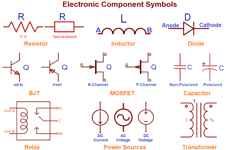
Electronic component symbols are used to denote the components in circuit diagrams. There are standard symbols for each of the components which represent that particular component. Here in this article, we are explaining some basic and mostly used electronic components with their symbols.
Resistor:

The resistor is a two-terminal component which is denoted by R. Symbol of the resistor is represented by Zig-Zag lines between two terminals. It is a common and widely used symbol in schematics. It can also be represented by another symbol that has an unfilled rectangle between two terminals instead of Zig-Zag lines. There are various types of resistors like a variable resistor, LDR, Thermistor, MOV, etc.
The resistor is a non-polarized component that means both sides have the same polarity and can be connected from both sides. The value of the resistor is measured in ohms (Ώ).
Capacitor:
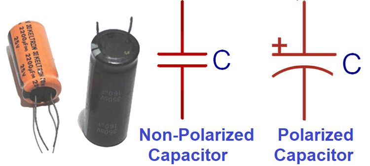
The capacitor is a two-terminal component denoted by C. Symbol of the capacitor looks like the two parallel plates are placed in between two terminals. In the schematic, two types of capacitor symbols are available. One is for a polarized capacitor and the other one is for the non-polarized capacitor. Learn more about capacitors here and check about various types of capacitors.
The difference between both the symbols is that in the polarized capacitor symbol, one parallel plate has a curved shape. The curved plate represents the cathode of the capacitor and should be at a lower voltage than the anode pin (plane-parallel plate). The plane-parallel plate is the anode of the capacitor and is marked by plus (+) sign.
As the name indicates, a non-polarized capacitor can be connected in two ways but for polarized capacitor only specified one-way Connection is possible. The value of the capacitor is measured in farads (f).
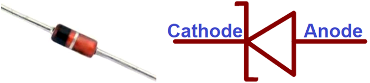
Diode:
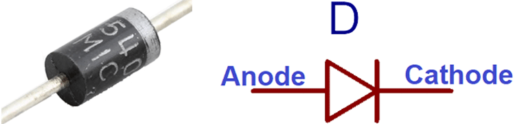
The diode is a polarized device with two terminals and denoted by D. In a diode, one terminal is positive (anode) and another one is negative (cathode). The closed side of a triangle is the cathode, and the base of a triangle is an anode.
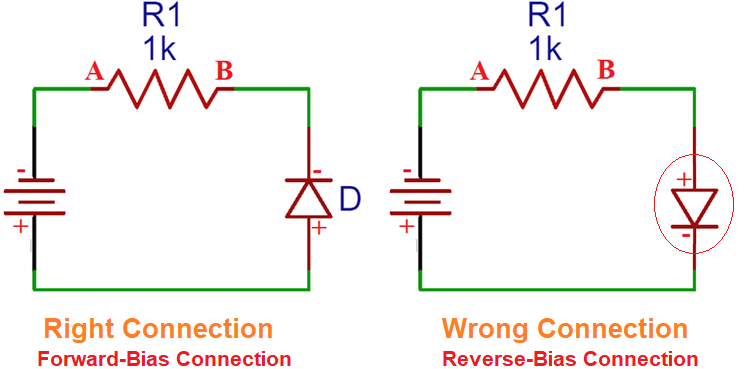
The symbol of a diode looks like a horizontal isosceles triangle pressed up against a line between two terminals. The diode works in the forward bias or we can say that the diode will let the current flow in the forward bias condition.
Therefore, it is important to note that the positive terminal (anode) of the diode is connected to the positive pole of the battery and negative pole (cathode) of the diode is connected to the negative terminal of the battery.
There are some other diodes with additional specifications and features explained below. Also, check various diodes and their working here.
Light Emitting Diode (LED):
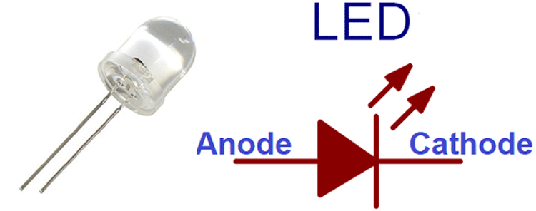
LED stands for light-emitting diode. The LED symbol is similar to the diode symbol with additional arrows. These arrows appear to point in the opposite direction of the triangle and seem to radiate from the triangle. LED is a polarized component with anode and cathode terminals.
Photodiode:
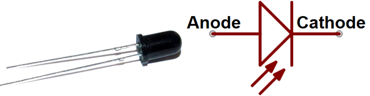
The symbol of the photodiode is similar to the LED Symbol except that it contains arrows striking the diode. Arrows striking the diode represent photons or light. The photodiode has two terminals named anode and cathode. A photodiode is used to convert light into electrical current.
Zener Diode:
It is similar to the normal forward diode; it also allows reverse current when the applied voltage reaches the breakdown voltage. The diode has a special, heavily doped P-N junction, which is designed to operate in the reverse direction when a certain specified voltage is reached.
Learn more about it by going through various Zener Diodes.
Schottky Diode:
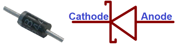
The Schottky diode has a lower forward voltage drop than the PN junction diode, and it is a metal-semiconductor diode. It can be used in high-speed switching applications. The Schottky diode is a unipolar device because it has electrons as majority carriers on both sides of the junction.
For this reason, electrons cannot flow across the Schottky barrier. Under the forward biased condition, an electron present on the N side receives more energy to cross the barrier and enter into the metal. Therefore, the diode is called a hot carrier diode. Due to this, the electrons are also called hot charge carriers.
Transistors:
In schematics, various transistors are available, either BJTs or MOSFETs. The transistor is a three-terminal device that amplifies or switches electronic signals and electrical power. We have previously covered various Transistors with their symbols, pinouts, and specifications.
Bipolar Junction Transistor (BJT):
BJT is a bipolar transistor with three terminals: emitter (E), base (B) and collector (C). For the BJT symbol, emitter and collector are arranged in a line and the base is arranged vertically. There are two types of BJTs: NPN and PNP.
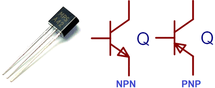
In the BJT symbol, the emitter has an arrow and the arrow's direction tells whether it’s a PNP or NPN transistor. If the arrow points inward, it is a PNP, and if the arrow points outward, it is an NPN.
To remember the configuration you can learn it like this- “NPN: Not Pointing In”
MOSFET:
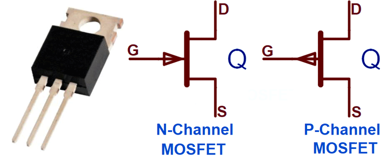
MOSFET stands for Metal Oxide Field Effect Transistor and it has three terminals named Source (S), Drain (D), and Gate (G). MOSFET has two types of symbols for n-channel or p-channel MOSFET. Here you can learn about various types of MOSFETs.
Just like BJT, in MOSFET, the direction of the arrow is used to distinguish between n-channel and p-channel MOSFET. If the arrow at the center of the symbol is pointing IN, it is an n-channel MOSFET and if the arrow is pointing OUT, it is a p-channel MOSFET.
You can remember the configuration like this. “n is IN”
Inductor:
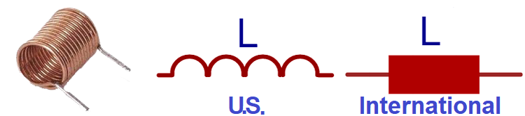
An inductor is a non-polarized two-terminal component. Inductor’s Symbol contains loopy coils or curved bumps in between two terminals. The international symbol of an inductor considers a filled-in rectangle instead of loopy coils. An inductor is denoted by ‘L’ and the unit is Henry (H). Here are few Inductors with their pinouts and working.
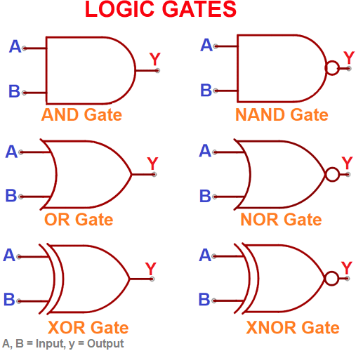
Digital Logic Gates:
Logic gates are the fundamental building blocks of any digital system. Logic gates have two inputs and one output however, the number of inputs can be changed as per the requirement while the output should be the same.
Usually, there are 4 standard logic gates available named AND, OR, XOR, and NOT. Moreover, adding a bubble to the output negates the function and generates NANDs, NORs, and XNORs.
All the logic gates have a unique schematic symbol as shown below.
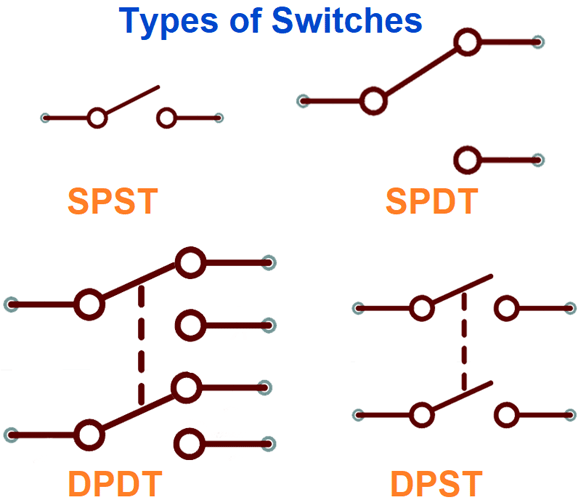
Switches:
Switches are electronic devices designed to interrupt or divert the flow of electric current or signals in a circuit. The simplest switch, a single-throw switch (SPST), consists of two terminals with a semi-connected lead representing the actuator.
In electronics, 4 types of switches are available named Single Pole Single Throw Switch (SPST), Single Pole Double Throw Switch (SPDT), Double Pole Single Throw Switch (DPST), and Double Pole Double Throw Switch (DPDT).
All 4 switches have different symbols, although the number of poles and throws changes in symbol according to their name. Symbols are given below to clear the illustration.
Power Sources:
The power supply is an essential part of any electrical or electronic system. While selecting an accurate power supply, various requirements must be considered.
There is a variety of power supply circuit symbols that indicate the power source.
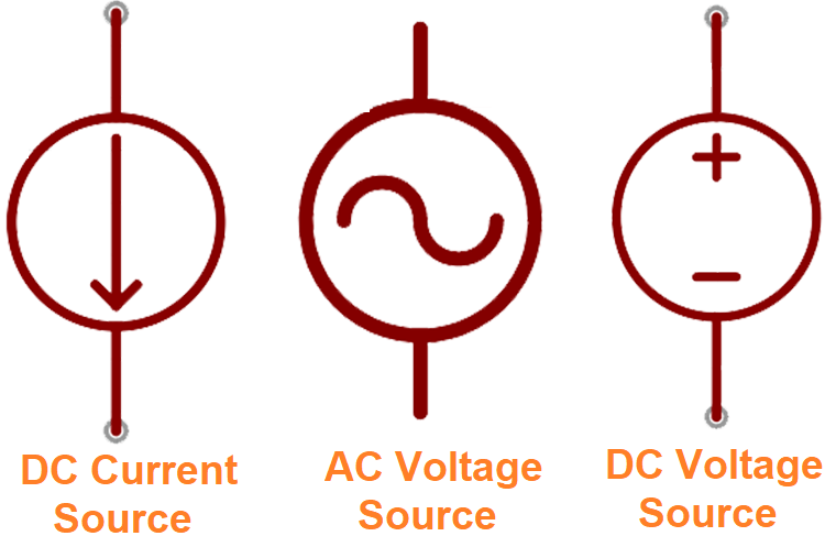
DC or AC Voltage Source:
Generally, constant voltage sources are used while working with electronics. We can use one of these two symbols to define if the source supplies Direct Current (DC) or Alternating Current (AC).
Batteries:
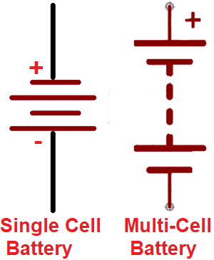
Instead of a constant voltage source, you can also use batteries. The battery symbol looks like a pair of disproportionate parallel lines, while more line pairs usually indicate more row cells in the battery.
Voltage Nodes:
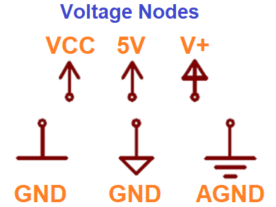
Voltage nodes are single-terminal schematic components that are used to denote power supply and can also be connected to component terminals to specify a specific voltage level. The device can be directly connected to this one-terminal symbol which denotes 5V, 3.3V, VCC or GND (ground). Positive voltage nodes are usually indicated by an Up-pointing arrow, while ground nodes typically include one to three flat lines or sometimes down-pointing arrows or triangles as shown in the image above.
Transformer:
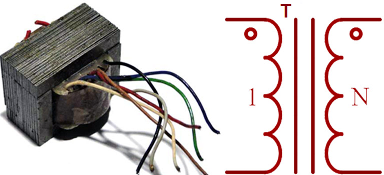
A transformer is a static device that transmits electrical energy from one circuit to another through electromagnetic induction. The transformer symbol is denoted by two coils placed side by side, and separated by parallel lines. They are generally used to step up or step down the voltage levels.
Relay:
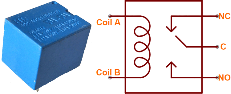
Relay is an electromagnetic switch that can be turned on with small electrical current which further allows a large amount of current to flow from it. It usually pairs a coil with a switch which can be seen in the symbol itself.
The relay has 5 pins consisting of a pair of coil pins, a common pin, a normally open pin (NO), and a normally closed pin (NC). We previously covered a detailed article on Relay and its working.
Buzzer and Speaker:
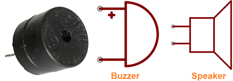
In buzzer, there is usually an oscillating transistor circuit, so it produces sound whenever a voltage is applied to it. The buzzer is a polarized component and can only be connected with a positive terminal to positive and negative to negative.
A speaker can play all kinds of sound. However, due to its integrated circuits, a buzzer is only able to compose the tone of the oscillator. Learn more about Buzzer and Speaker by following the links.
Motor:
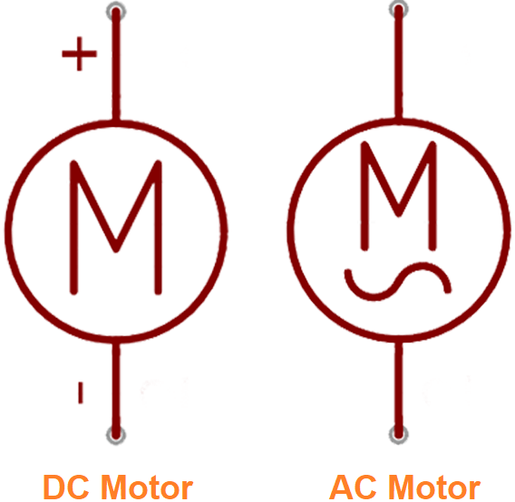
The motor is a transducer that converts electrical energy into kinetic energy (motion). The motor symbol looks like an embellishment encircled 'M' around the terminals.
We have covered various types of motors with their symbol and working.
Fuse and PTCs:
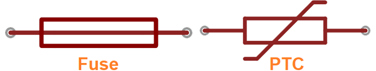
A fuse or a PTC is an electrical safety device that provides overcurrent protection for a circuit. The PTC symbol is actually the general symbol for a thermistor.
Below table shows the unit, pin name and no of terminals of all the components we covered above:
|
Component |
Denoted by |
Unit |
Polarity/Pins |
Terminals |
|
Resistor |
R |
Ohms(Ώ) |
Not |
2 |
|
Capacitor |
C |
Farads(f) |
Anode-Cathode |
2 |
|
Diode |
D |
|
Anode-Cathode |
2 |
|
Inductor |
L |
Henry(H) |
Not |
2 |
|
Transistors(BJT) |
NPN/PNP |
- |
Emitter, Base, Collector |
3 |
|
Transistor(MOSFET |
n-Channel P-Channel |
- |
Drain, Source, Gate |
3 |
|
Relay |
- |
- |
NC, NO, C, 2-Coil Pins |
5 |
|
Power Sources |
- |
Voltage, Current |
Positive, Negative |
2 |
|
Motor |
M |
RPM |
Positive, Negative |
2 |
So this is a beginner guide to learn about different types of basic electronic components, their symbols, and working.


