LDR (Light Dependent Resistor) or Photoresistor
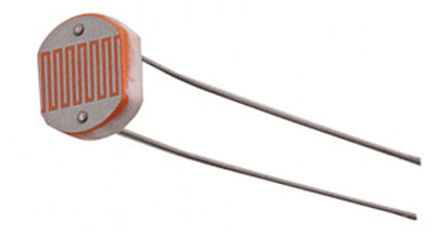
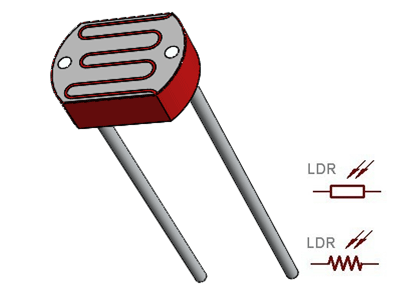
The Light Dependent Resistor (LDR) or also popularly known as Photoresistor is just another special type of Resistor and hence has no polarity so they can be connected in any direction. They are breadboard friendly and can be easily used on a perf board also. The symbol for LDR is similar to Resistor but includes inward arrows as shown above in the LDR pinout diagram. The arrows indicate the light signals.
LDR Features
- Can be used to sense Light
- Easy to use on Breadboard or Perf Board
- Easy to use with Microcontrollers or even with normal Digital/Analog IC
- Small, cheap and easily available
- Available in PG5 ,PG5-MP, PG12, PG12-MP, PG20 and PG20-MP series
Note: More technical Details and sample circuits can be found at LDR Datasheet given below
Other Resistor based Components
Higher Power Resistor, Potentiometer (Variable Resistor), Thermistor.
Where to use a LDR
A photoresistor or LDR (Light Dependent Resistor), as the name suggests will change it resistance based on the light around it. That is when the resistor is placed in a dark room it will have a resistance of few Mega ohms and as we gradually impose light over the sensor its resistance will start to decrease from Mega Ohms to few Ohms.
This property helps the LDR to be used as a Light Sensor. It can detect the amount of light falling on it and thus can predict days and nights. So if you are looking for a sensor to sense light or to distinguish between days and nights then this sensor is the cheap and modest solution for you.
How to use a LDR Sensor
As said earlier a LDR is one of the different types of resistors, hence using it is very easy. There are many ways and different circuit in which an LDR can be used. For instance it can be used with Microcontroller Development platforms like Arduino, PIC or even normal Analog IC’s like Op-amps. But, here we will use a very simple circuit like a potential divider so that it can be adapted for most of the projects.
A potential Divider is a circuit which has two resistors in series. A constant voltage will be applied across the both the resistor and the output voltage will be measured from the lower resistor. In our case, the lower resistor will be a LDR and the constant voltage will be +5V. The set-up is shown below
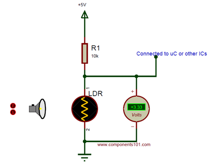
A DC multimeter is used to monitor the voltage across the LDR. As the Lamp is moved towards the resistor the resistance value of the LDR will decrease as a result the voltage drop across it will decrease. The near you bring the Lamp the lower the voltage will get and the farther you move away your Voltage value will increase. The working simulation is shown below.
Now that we have understood how the LDR provides a variable voltage based on Light, we can feed this voltage either to a Microcontroller and use ADC to convert the Voltage to meaning full data or use a Op-amp as a Voltage comparator and trigger an specific output like LED or Buzzer for a specific Voltage from the LDR.
Applications
- Automatic Street Light
- Detect Day or Night
- Automatic Head Light Dimmer
- Position sensor
- Used along with LED as obstacle detector
- Automatic bedroom Lights
- Automatic Rear view mirror
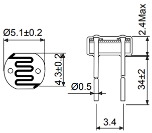
2D – Model of LDR (PG5)