

Optimized with highly sensitive cap touch sensors, extensive peripheral circuits and 125℃ operation
Introduction to Capacitors: Basic Concepts, Working, Types and Applications in Circuits

Capacitors – the word seems to suggest the idea of capacity, which according to the dictionary means ‘the ability to hold something’. That is exactly what a capacitor does – it holds electric charge. But what makes it a common component in almost all electronic circuits? Let us break down the stuff behind capacitors to understand what it does and how one could use them in this article.
What is a capacitor?
A capacitor in its most primitive form consists of two conductive plates separated by a dielectric medium. The term dielectric is just a fancy word for an insulator that can be polarized, i.e. form negative and positive charges on opposite faces. When voltage is applied across these two plates, current flows through the conductive plates. One side gets positively charged (lack of electrons) and the other side gets negatively charged (excess electrons). We’re all familiar with the fact that unlike charges attract, so since the plates are oppositely charged, the charges on the plates attract.
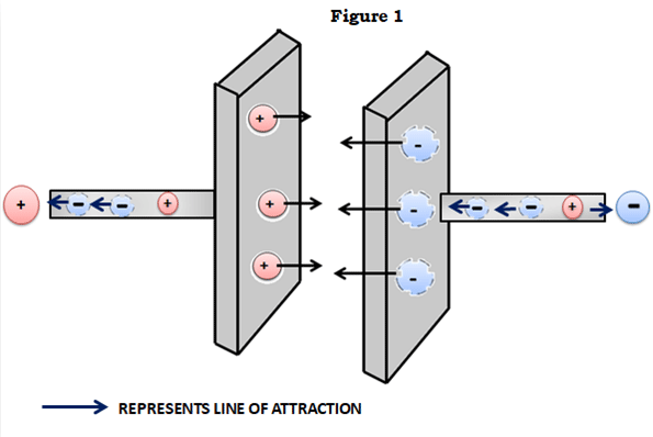
Remember that there’s an insulator between the plates, so the charges cannot ‘flow’ to equalize each other and are (ideally) stuck in a state of mutual attraction and stay put. And that is how capacitors carry out their most basic function – retention or storage of charge.
Symbol of Capacitors
Since the capacitors have two parallel metal plates as discussed above, their symbol kind of represents the same. At least it’s easy to draw
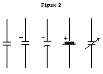
In a practical case, Capacitors are no longer just two plates with a gap between them, in the case of aluminium electrolytics the two plates take the form of metal foil rolled up with a spacer between them in a tube.
The second set of symbols stand for polarized capacitors, meaning ones which have defined positive and negative terminals by internal design. Accidentally reversing these terminals will almost certainly result in a spectacular failure (especially for larger specimens), ejecting bits of foil and paper meters from the site of failure and most of the time smelling very bad.
Capacitance and Voltage Rating for a Capacitor
Capacitors are measured in Farads; it is named after the famous British electrochemist, Michael Faraday. The unit of capacitance, standing in for Coulomb per Volt. The Coulomb (pronounced ‘koo-lom’) is the S.I. unit for charge, and a Volt, as we know, is the unit for voltage or potential difference. That makes the Farad the amount of charge stored per Volt of potential difference. This simple way of looking mathematically at a capacitor lends itself to a wide range of interpretation, manifested by a lot of deadly complex math equations stuff like integrals and exponents and vectors which we engineers will use while working with capacitors, that is something way beyond the scope of this article. However, we’ll get into a little interesting math that’ll help us design circuits with capacitors later in the article
Of course, the Farad (one Coulomb per Volt) is a very large unit for most practical purposes (since the Coulomb itself is a rather large amount of charge, as you might already know), so most capacitors (except for very large ones) are measured in microfarads, or one-millionth (0.000001) of a Farad. Suppose you have a capacitor that reads 25V 10uF (the ‘u’ prefix stands for micro, it’s a corruption of the Greek symbol µ (‘mu’) meaning ‘micro’) on the plastic outer cover. Since the cap (short in the electronic world for capacitors) is rated for 10uF, it can hold a charge of ten micro coulombs (that is, ten millionths of a Coulomb, 0.000010 C) per volt of voltage across its terminals. That means, at the maximum voltage of 25V, the capacitor can hold a charge of 25V x 10uF, which works out to be 0.000250 Coulombs.
Remember I said ‘maximum’ voltage. Max voltage is probably the most important rating on the capacitor. It tells you how much voltage a capacitor can handle across its terminals before it goes KABOOM………!
Working of a Capacitor
Basically what is happening inside a capacitor is that the insulator between those plates is undergoing a process called ‘dielectric breakdown’, meaning the insulator can no longer insulate since the voltage across the insulator is too high for it to be able to remain an insulator. The underlying physics is somewhat off scope, but all you need to know to understand why this happens is that no insulator is prefect, that is, up to a certain point. Even the strongest bridge collapses if it is overloaded. What happens here is similar. To reduce breakdown, you might increase the gap between the two plates, but that comes with a trade-off – reduced capacitance, since the plates are further apart and charges do not attract as much as they do when they are closer – much like the way magnets behave.
A good rule of thumb would be to use caps rated for a 50% greater voltage than what your circuit might be expected to see. This leaves a wide safety margin. For example, if you need a cap to decouple (worry not, decoupling is explained later in the article) a 12V power supply rail, you could get away with using a 16V capacitor, but using a 25V capacitor is recommended since it gives you a wide safety margin. Okay you found it out!! Yes 25V is, of course, not 25% greater than 12V, but 18V is not a standard capacitor value - you won’t find any with that voltage rating. The nearest is 25V.
Different Types of Capacitors
The reason for the breakdown voltage ranges is because of the material used as a dielectric, which is also the basis on which capacitors are classified:
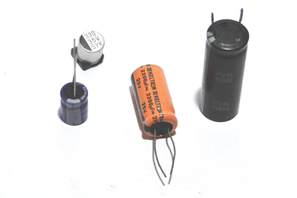
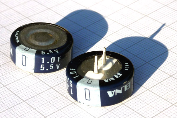
Aluminium Electrolytic Capacitors
These are probably the most recognizable types of capacitors. They come in distinctive metal cans with a plastic sheath, with clearly stated voltage and capacitance ratings and a white band to indicate the cathode. The name comes from the fact that, like mentioned above, the ‘plates’ are made of chemically etched aluminum foil. The etching process makes the aluminium porous (much like a sponge) and increases its surface area greatly, hence increasing capacitance. The dielectric is a thin layer of aluminium oxide. These capacitors are filled with oil that acts like an electrolyte, hence the name. Electrolytic capacitors are polarized because of their internal construction. They have large capacitance compared to other members of the capacitor family, but much lower voltages. You can expect to see electrolytics between 0.1uF to monsters like 100mF and with rated voltages of a few volts to around 500V. Their internal resistances, however, tend to be high.
SIDE NOTE: Internal resistance in capacitors is due to the materials which the cap is made of – for example the resistance of the aluminium foil or the resistance of the leads.
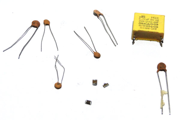
Ceramic Capacitors
These are caps with a ceramic dielectric. Since the breakdown limit for the ceramic dielectric is quite high, you can expect to see ceramic caps with crazy breakdown voltages like 10kV. However, capacitance tend to be low, in the range of picofarads (0.000000000001F) to a few tens of microfarads. They are generally a lot smaller than other types of capacitors, as shown in the picture. They also have very small internal resistances.
Identifying Ceramic Capacitors
The value of a ceramic capacitance will not be directly mentioned on the ceramic capacitor. There will always be a three digit number followed by a variable; let’s learn how to identify the value using these numbers. Consider the following capacitor.
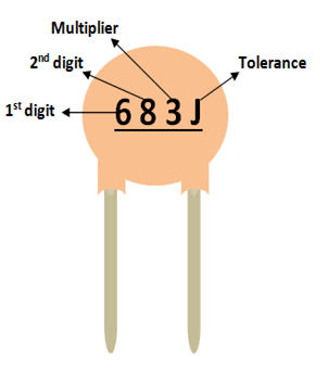
As you can notice, these three digits are split into two digits and the third one is the multiplier. In this case 68 is the digit and 3 is the multiplier. So 68 should be multiplied with 10^3. Simple put it is 68 followed by 3 zeros. Hence the value of this capacitor will be 68000 pF. Notice the unit should always be pF. Similarly a capacitor with 220 code means it is 22 Pico farad, since 10^0 is 0.
The voltage rating of the capacitor can be found by using the line under this code. If there is a line then the voltage value is 50/100V if there is no line then it is 500V.
The most commonly used capacitor values along with their conversion in Pico Farad, Nano Farad and microfarad is given below.
|
Code |
Picofarad (pF) |
Nanofarad (nF) |
Microfarad (uF) |
|
100 |
10 |
0.01 |
0.00001 |
|
150 |
15 |
0.015 |
0.000015 |
|
220 |
22 |
0.022 |
0.000022 |
|
330 |
33 |
0.033 |
0.000033 |
|
470 |
47 |
0.047 |
0.000047 |
|
331 |
330 |
0.33 |
0.00033 |
|
821 |
820 |
0.82 |
0.00082 |
|
102 |
1000 |
1.0 |
0.001 |
|
152 |
1500 |
1.5 |
0.0015 |
|
202 |
2000 |
2.0 |
0.002 |
|
502 |
5000 |
5.0 |
0.005 |
|
103 |
10000 |
10 |
0.01 |
|
683 |
68000 |
68 |
0.068 |
|
104 |
100000 |
100 |
0.1 |
|
154 |
150000 |
150 |
0.15 |
|
334 |
330000 |
330 |
0.33 |
|
684 |
680000 |
680 |
0.68 |
|
105 |
1000000 |
1000 |
1.0 |
|
335 |
3300000 |
3300 |
3.3 |
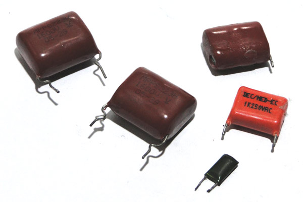
Film capacitors
As the name suggests, the dielectric in these capacitors is a plastic film, often familiar plastics such as mylar and polyester. They have the same properties as ceramic caps, high breakdown voltages (because of the way the plastic polymers behave) and low capacitances. The only difference is that they tend to be slightly larger though they look superficially like ceramic caps. Internal resistance is comparable to ceramic caps.
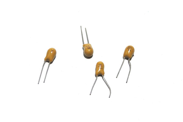
Tantalum and Niobium capacitors
These caps technically fall under the electrolytic category of capacitors. Here, the electrolyte is a solid material made of tantalum or niobium oxides. They have very low internal resistance for a given capacitance, however they are less immune to overvoltage compared to other types (ceramic has the best) and tend to go kaput without much warning and with a lot of nasty black smoke.
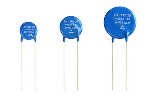
Special purpose capacitors
These include silver – mica caps, X and Y rated caps, etc. X and Y rated capacitors, for example, are built for line filtering – more robust construction and higher voltage ratings, also low capacitances, to reduce the current passing through it if AC voltage is applied and to limit the energy stored in the cap if DC voltage is applied.
Supercapacitors and ultracapacitors
They take capacitors to a whole new level, with largely increased capacitances, sometimes in the range of hundreds of Farads! This is possible because of some clever chemistry. Supercapacitors and ultracapacitors bridge the gap between capacitors and chemical batteries. They come in very low voltages, however.
And those are pretty much all the common types of capacitors you might commonly encounter in the world of electronics.
How Capacitors Behave in Circuits
A useful first task would be to learn how to calculate the energy stores in a capacitor, which is given by the formula,
E = 1/2CV2
Where E is the energy stored in Joules, C is the capacitance in Farads and V is the voltage in Volts. Note that this equation takes the form of many other Newtonian equations for energy, a neat easter egg!
Supposing you have a cap rated for a voltage of 50V and with a capacitance of 1000uF, the stored energy at the full 50V would be:
1/2 * 0.001000F * 50V * 50V
Which works out to be a measly 1.25J of stored energy.
This reveals a major disadvantage of capacitors as energy storage devices – the stored energy for a given size is very low, a battery of the same size would have at least a thousand times more stored energy! However, caps have greatly lower internal resistances than chemical batteries, which enable them to dump all their stored energy quickly. Shorting a battery would only cause it to heat up because of the power dissipated by the internal resistance, but shorting a capacitor would only create a few sparks since all the charge is dumped at once without damage to the capacitor.
Second, there is another neat formula that relates voltage, current and capacitance:
I/C = dV/dt
Where I is the current supplied to the capacitor in amps, C is the capacitance in Farads and dV/dt is the rate of change of voltage across the capacitor terminals. Think of this in terms of its unit – volts per second for a given current and capacitance. Don’t worry about the little ‘d’, it’s just a mathematical way of saying ‘to the limit zero’.
Let’s say you have a power supply that spits out a constant voltage of 5V at a constant current of 1mA, then on rearranging the equation we can find the time taken to charge a 100uF capacitor to 5V:
dt = CdV/I
dt = (0.000100F * 5V)/0.001A
dt = 0.5 seconds
So the capacitor would charge up to 5V in 0.5 seconds. (Remember that a capacitor can only charge up to the maximum voltage supplied to it, never more, they cannot magically ‘create’ voltage.)
This predictable behavior of a capacitor makes it very useful for generating time delays, for example, with a little additional circuitry. You can rearrange the equation to obtain time.
Now for the good stuff – actual capacitor circuits!
Capacitor Behavior in Circuits
Let’s begin simple – the different ways capacitors can be connected together. It’s much the same as connecting two resistors – you can either connect them in series or parallel.
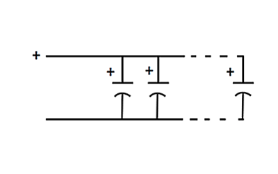
Capacitors in Parallel
The figure below shows three capacitors connected in parallel, with all the respective positive and negative terminals connected together (assuming the caps are polarized). The total capacitance of this arrangement is simply the sum of all the capacitances of all the capacitors in the circuit. This makes sense, since connecting the capacitor plates in parallel increases the surface area, increasing the capacitance.
The maximum voltage this sort of arrangement can handle is the voltage of the smallest capacitor, since in the voltage is common to all the caps.
An example should clear this up. Supposing you have two capacitors, one with the ratings 25V 470uF and the other 35V 1000uF. The total capacitance would be 470uf + 1000uF = 1470uF. However, the maximum voltage you could put across this bank (a bunch of capacitors connected together can be called a capacitor ‘bank’) would be just 25V. If you put anything higher than that across this bank, sparks would fly, since you exceed the max. voltage of the 25V capacitor.
Capacitors in series
Connecting capacitors in parallel is particularly useful when you want a large capacitance and you have only small values. Putting together those smaller value caps in parallel will eventually get you the larger value and do the job, assuming you are mindful of voltage.
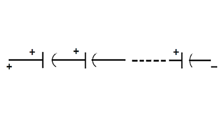
Now putting capacitors in series is a little more complicated. The capacitance is given by the formula:
1/Ctotal = 1/C1 + 1/C2 + … + 1/Cn
Where C1, C2…Cn are the capacitances of each capacitor used in the circuit.
The voltage the bank can now handle is the sum of all the rated voltages.
If you’re given a cap rated for 10V 1uF and a cap rated for 50V 10uF, then the voltage the bank can handle in series is 10V + 50V = 60V. The capacitance works out to be 0.9091uF.
Capacitor Voltage vs Time
What if we want to charge a capacitor? We could just connect it across a voltage source, like in figure below. What would happen here is that the moment the voltage source is connected, assuming the cap is completely discharged, charges rush to accumulate on the plates, leading to a very large (in theory, infinite!) current spike limited only by the internal resistance of the capacitor. This is not desirable, of course, if your power supply happens to be something like a battery. A sensible idea would be to add a resistor in series with the capacitor and the voltage source to limit the current like in Figure, and voila! You have something engineers call an RC circuit, ‘R’ for resistor and ‘C’ for capacitor!
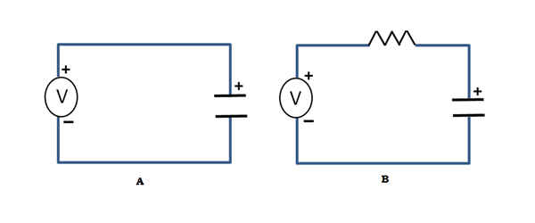
This circuit shows some interesting behavior. When the voltage is connected to the side of the resistor marked ‘I’, the voltage on the capacitor rises slowly since the current is limited. The graph looks something like this:
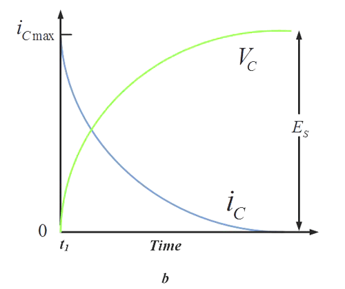
The more mathematically inclined of my viewers would recognize the shape of the slope – it resembles that of the exponential function!
Remember how I said caps could be used to generate time delays? This is one way of doing that without a constant current source (which needs some additional circuitry). Since the time taken to reach a particular voltage is predictable if we know the capacitance, voltage and resistance, we can create time delay circuits.
The product of resistance and capacitance, RC, is known as the time constant of the circuit. This parameter becomes useful in actually determining the time to reach a given voltage accurately, as shown by the graph figure below.
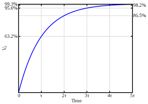
From the graph you can see that the capacitor reaches 63% of the applied voltage in one time constant, and so on.
This is the principle the all-season 555 timer uses, though the design equations are a little different.
Another interesting application of RC circuits is signal filtering, i.e. removing an electrical signal of an unwanted frequency from a circuit. The RC circuit takes a given amount of time to charge and discharge from a source. If we apply a periodic wave with a time period greater than RC, then the same signal would appear on the output with very little distortion. However, on increasing the frequency, the signal keeps changing polarity faster than the circuit can charge and discharge, and eventually after a certain point, the signal vanishes, and all you are left with is clean DC! This is called signal attenuation. As you can see an RC circuit acts like a filter that blocks AC signals (even ones superimposed on DC, i.e. having a DC offset) beyond a certain frequency. This kind of filter is called a low-pass filter, that is, it lets low frequencies pass through but does not let high frequencies through.
Capacitors in Ac circuits
Capacitors behave in an interesting way when placed in AC circuits. They can be thought of as frequency dependent resistors, from the signal point of view. As seen above, the RC circuit blocks all AC from a signal, but what happens when a capacitor is connected in series with an AC voltage source? The exact opposite!
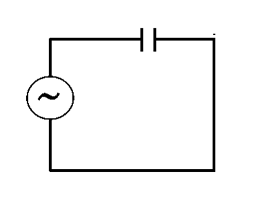
Since the capacitor is just two metal plates separated by an insulator, it does not let any DC current pass through it. However, an Ac signal has constantly changing voltages, so one plate sees a changing voltage and induces the opposite charge on the other plate, as shown in the figure:
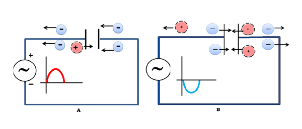
This has the overall effect of letting current ‘pass’ through the capacitor at relatively high frequencies. The addition of a resistor in parallel with the output makes a high-pass filter, i.e. a filter which lets through only high frequencies and blocks all DC signals.
The ‘AC resistance’, or impedance, of a capacitor, is given by the formula:
XC = 1/(2*π*f*C)
Where XC is the capacitive reactance or impedance, f is the frequency and C is the capacitance. You can use this formula to calculate the virtual ‘resistance’ a capacitor has in an AC circuit.
Where Capacitors are Found in the Wild
Okay, that was enough theory. Let’s look into the many uses of capacitors.
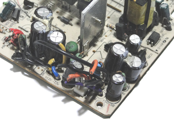
The first place you might expect to see capacitors are in power supplies of all sorts as filters and for decoupling. They act as charge reservoirs – providing quick current when the load needs it.
Here are two oscilloscope shots that show the effect of not having and having a capacitor across the leads of a power supply. As you can see, having capacitors dramatically reduces the ‘noise’ on the power supply rails, thus protecting delicate parts from sudden voltage spikes.
They’re also called ‘decoupling’ capacitors, since they ‘decouple’ sections of the circuit across which they are mounted from the power supply. Sometimes the power leads on a circuit board might be quite long and have a high inductance and resistance. This can lead to them providing less current than usual. Having a capacitor at the end of the supply line is like having a smaller temporary ‘battery’ across the device, providing bursts of current when needed and charging up when the device consumes low power.
You can use the formula I/C = dV/dt to calculate the necessary capacitance to remove ‘ripple’ voltage from the power supply terminals.
Suppose you have a power supply whose voltage varies from 11.5V to 12V (ripple) every 10ms, which is common in mains powered devices due to the 50Hz frequency, and you need to place a cap across the terminals to smooth out the voltage. If the load current in this case is 1A, then we can rearrange the formula this way to find out the capacitance:
(I * dt)/dV
Where I is the load current, dt is the time period of the noise, and dV is the ripple voltage. Substituting the values, we find that we need a capacitance of 20000uF. Now this may seem like a lot, but you could get away with much less. The value obtained only serves as a guideline.
In real life you might find multiple types and values of capacitors across power traces, this is to reduce the noise content across many frequencies and have the smoothest voltage possible.
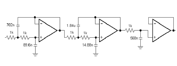
Another use of capacitors are in complicated filters like this one:
But a simpler filter would be the RC filter, one interesting filter is described here.
Everyone knows the Arduino microcontroller board. A versatile tool, but haven’t you ever wondered why the analog outputs spit out a digital PWM signal? That’s because they were designed to be used with an external filtering network to smooth out the PWM voltage to a truly analog voltage. This can be done with parts as simple as a 1K resistor and a 10uF capacitor. Try it!
Another use, like mentioned above, is timing. A simple oscillator can be built using a NAND gate (try figuring out why AND gates won’t work), a resistor and a capacitor.
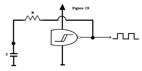
Assuming that there is initially no voltage across the capacitor, the NAND inputs (which are tied together) see close to 0V across them, and turn the output on. The cap now charges through the resistor. When it reaches the ‘high’ threshold of the gate, the output flips low and the cap now discharges. This cycle continues to produce a square wave output with a frequency dependent on the values of R and C.
Finally, another interesting use of capacitors is energy storage. Of course, capacitors are no match for batteries, but for some applications which need the energy quickly, caps are the best for the job.
Devices like coilguns (more can be found on the web) need a large pulse of current to accelerate the projectile, so high voltage capacitors are used for purposes like this, often with ratings such as 450V 1500uF, which can store significant amounts of energy.
Conclusion
So there’s that! You now know significantly more about capacitors than what you started out with. You are now capable of designing simple capacitor circuits. Remember, there’s a lot more to learn, and don’t switch the power supply terminals!


