

Optimized with highly sensitive cap touch sensors, extensive peripheral circuits and 125℃ operation
Introduction to Resistors
There is a very high chance that the first electronic component you might have encountered is the humble resistor, pretty and bead-like with bands of colors. Resistors are the simplest electronic component around and in many cases are brand ambassadors, so to speak, for the world of electronics.
It is almost inevitable to design a circuit without the use of a resistor. So in this article we will see what exactly are resistors and what they have to do in an electronic circuit. We will also cover the types of resistors that you can use in your circuits.
What is a Resistor?
A resistor, from the point of view of math, is the simplest implementation of Ohm’s law.
The law says the current flowing through a material is directly proportional to voltage applied across that material and the proportionality constant is the resistance of the material at a constant temperature.
In other words,
V = IR
Which is the classic formula we are all familiar with, where V is the voltage in Volts, I is the current in Amps and R is the resistance.
Resistance is measured in Ohms, after the discoverer of the formula. Since the Ohm is (for a change!) a rather small quantity circuit-wise, resistors are measured in hundreds of Ohms, thousands of Ohms (kiloOhms, kΩ), or millions of Ohms (megaOhms, MΩ).
Resistance is analogous to friction. Friction (if you’ve been to a physics class) is simply resistance offered to motion. In the same way, resistance is the ability of a substance to resist the flow of electric current. In the next section we shall learn how they do this.
How does a resistor work?
We’ve all spent our schooldays talking about conductors and insulators. We know what a conductor is, something that allows electricity to flow through it easily. The insulator is the exact opposite – something that does not let current low through it easily.
These properties are a direct result of resistance – conductors have a low resistance to the flow of electric current whereas insulators resist the flow of electric current to a large degree.
If we zoom right into a wire down to the atomic scale, we can see that the wire is made of tiny atoms.
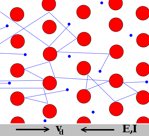
When electrons flow through the wire, some of them pass right through the gaps in the wire, but some of them hit an atom and bounce back, sometimes electrons themselves collide. This makes the flow of electrons somewhat non-uniform and impeded – this is resistance.
This also means that resistance depends on the properties of the material itself, since the interaction of the electrons with the atoms depends on the size and packing of the atoms.
People talk about temperature coefficients. While this may sound a little fancy, we can use our simple model to understand this.
Temperature coefficient is simply how and how much the temperature of a material changes with temperature. Resistors have a positive temperature coefficient, in other words the resistance increases with temperature. Now PTCs and NTCs make a lot more sense, don’t they?
Considering our model, when we heat the wire, we are (thermodynamically speaking) supplying energy to the wire. This energy is absorbed by the atoms which then start vibrating. This makes it more difficult for the electrons to get through.
It’s like moving through a crowd – the task is infinitely more difficult if the crowd is moving in a random direction than when the crowd is still (which is a practical impossibility).
Resistor Symbol
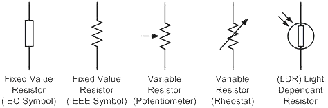
The symbol of a resistor is a simple zig-zag. In some countries people prefer using a box, but both symbols are accepted in the electronics community.
The second set of symbols are variable resistors or rheostats, resistors whose resistance can be varied within a certain range.
A Simple Resistor Circuit and Basic Formulas
Before we go any deeper it would be a nice idea to walk through a really simple resistor circuit to know what we are dealing.
Consider the following case – you have a green LED with a maximum current of 20mA and you want it to run off a 9V battery.
Connecting the LED directly to the battery might seem like a nice idea, but the moment the leads of the LED touch the battery terminals…KABOOM! The LED blows up. If you’re lucky, the LED will be gone in a flash, if you’re not so lucky you’ll end up with a lot of burnt LED matter.
What happened here is a simple case of overcurrent. When you first connected the LED to the battery, some current began flowing. This value was greater than the required 20mA, so the LED dissipated this as heat. As the LED heated up, its resistance decreased (negative temperature coefficient!) and that allowed more current to flow through it and this cycle continued till the semiconductor die couldn’t handle the heat and blew up.
What if we connected a resistor? We know from Ohm’s law that V = IR, if we rearrange the equation so:
R = V/I
Since we know the voltage of the power supply and the current required to safely light the LED. We plug in these values and we get a resistance of 450Ω. Now 450Ω is not a common value, so the nearest value of 470Ω should suffice.
There’s another way of doing this:
We know that a green LED has an operating voltage of about 3.5V and the battery voltage is 9V. So we would need to drop 5.5V across the resistor at 20mA. This leads to a value of 275Ω.
This is lower than the first calculation, which is because we take into consideration the forward voltage of the LED this time.
Now where does all this energy go? Just like friction generate heat, resistance generates heat too.
Going back to our model, electrons colliding with the atoms increases the energy of the atoms and in bulk increases temperature.
We know that:
P = VI
Solving for either V or I and then substituting the values in the equation for Ohm’s law we get two useful equations:
P = I2R = V2/R
Where P is the power dissipated in Watts, I is the current in Amps, V is the voltage in Volts and R is the resistance in Amps.
Of course, the resistor should be able to handle the amount of power we waste through it, and that means that resistors come in a variety of shapes and sizes:
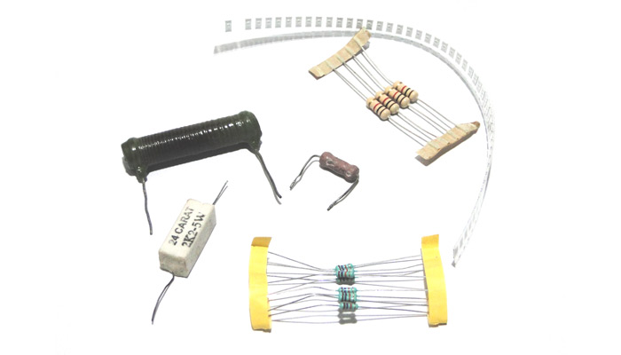
Through Hole Resistors
Saying ‘through hole’ might be a generalization, but if we categorically sorted all resistors by shape and size we would end up with a nearly endless list.
Through hole resistors, along with the resistance, are rated according to the power they dissipate. Probably the tiniest are 1/8W resistors, meaning they can dissipate 1/8 of a Watt or 125mW. On the other end of the scale you can find resistors that dissipate a massive 100W.
Variable Resistors (Potentiometer)
Variable Resistor a.k.a potentiometers as the name suggests is used to vary the value of the resistor as required. There are many types of variable resistors, you might have probably noticed the big knob types variable resistors on old radios to tune the stations or control the volumes. Apart from this there are small variable resistors called trimmers which are used to fine tune or calibrate an electronic circuit after the design is complete.
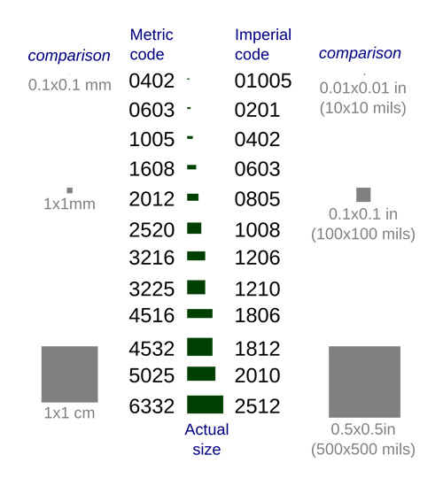
SMD Resistors
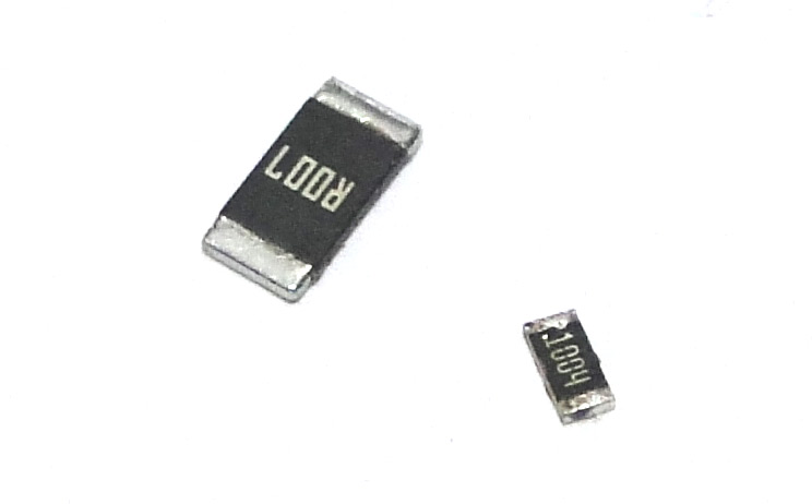
SMD stands for surface mount device. These resistors are designed to be soldered to the surface of PCBs and are tiny. They come in various sizes which can dissipate different powers.
Different Types of Resistors
Apart from coming in various shapes and sizes, resistors are also classified according to what the active material is made of.
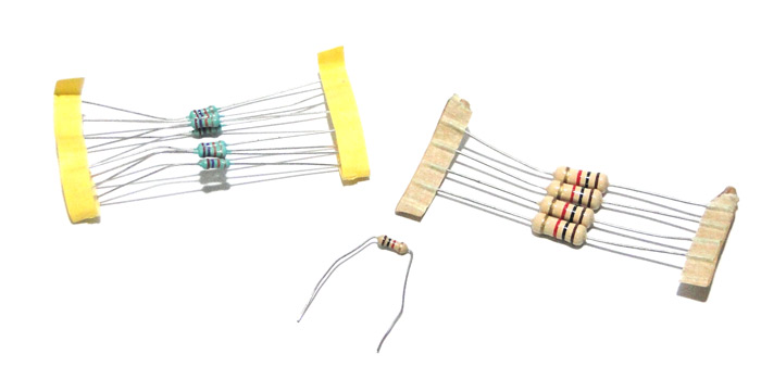
Carbon Resistors
The resistive material in these resistors is made of carbon or graphite dust. Since carbon compounds burn easily, these resistors can handle only low amounts of dissipated powers. Also since the material is a powder, they are not very accurate and have loose tolerances.
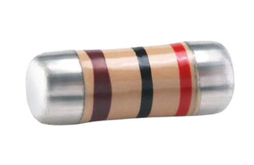
Metal Film Resistors
Just like their name suggests, the resistive material is a metal film. Since the metal film can be made or calibrated to very specific dimensions, the resistance can be controlled finely and as a result these resistors are very accurate.
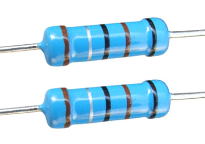
Wire Wound Resistors
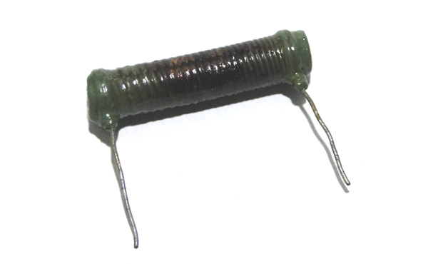
The resistive material is made of a wire. Since these wires can be as thick as one likes, these resistors can be made to handle very high powers and are often wound around a ceramic core as shown.
Semiconductor Resistors
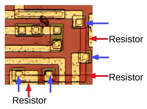
These resistors are implemented in silicon and form an integral part of semiconductor ICs.
Uses Of Resistors
The simplest most often have the most uses, and the resistor follows this statement exactly.
1. Current Limiting: As seen above, resistors can be used to limit the current that flows into a device.
2. Voltage dividers: This makes use of two resistors to divide a voltage by the ratio of their resistances. This is my favorite image to show people when they ask about voltage dividers:
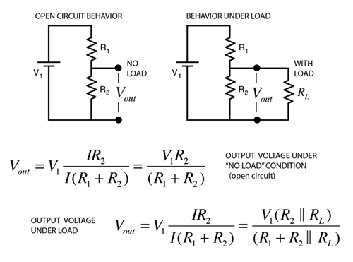
These circuits are really useful. Suppose you have a 5V power supply and you want to power a 3.3V device, you can use a voltage divider.
They also allow you to measure high voltages by scaling them down. This fact is used by the humble multimeter; the rotary switches on older models were connected to voltage dividing resistors that enabled you to select a scale so that the reading stayed within the range of the analog meters.
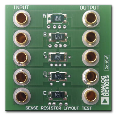
3. Current shunts: These are low value resistors that are used to measure currents without interfering much with the circuit under test. They have low resistor values and high power rating. In this method the current to be measured is allowed to pass through the resistor and the voltage drop across the resistor is measured. Once we know the voltage drop and the resistor value, we can use the ohms law (V=IR) to calculate the value of current.
4. Pull up and Pull down resistors: A pull up or pull down resistors are normally used in digital circuits to define the default status of the pin. Consider a microcontroller input pin for example, when there is no voltage applied or circuit is connected to this the pin can read either 1 or 0 this condition is called as floating pin. To avoid this situation the pin is usually pulled up by connecting a resistor to vcc or pulled down by connecting a resistor to ground. The value of resistor here will be normally 10k.
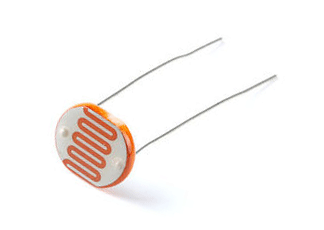
5. Sensors: It might be suppressing, but most simple sensors are nothing but variable resistors. Some examples would be LDR, Flex Sensor etc.
An LDR for example are special resistors whose resistance varies with the amount of light that falls on them. The resistive material which gives them this special property is cadmium disulfide. They are used in things like night lamps and dark detectors.
Things to keep in mind while using a resistor
1. Power dissipation: Again, never select a resistor that has a power rating less than what you are going to put through it. A good rule of thumb would be to choose a resistor with a power rating at least two times higher.
2. Temperature coefficients: This is very important to keep in mind when dealing with resistors that are used with high current or high temperatures since the resistance drifts quite drastically. There are two types of temperature co-efficient one is called NTC (Negative Temperature coefficient) and the other is called PTC (Positive temperature Coefficient). For NTC the resistance of the resistor will decrease as the temperature around it increases and for a PTC the resistance of the resistor will increase as the temperature around it increases. This property is also used by some sensors like Thermistors to measure temperature.
Conclusion
Resistors, as simple as they may seem, but their applications are endless you can even build a DAC (Digital to analog converter) but just using resistor (R2R) method. Be it a simple Op-amp gain circuit or a complex switching circuit Resistor play a vital role. We have touched all the basics of resistors in this article and this should make you feel comfortable while trying to analyze the function of a resistor when you look at a circuit.


