

Optimized with highly sensitive cap touch sensors, extensive peripheral circuits and 125℃ operation
Introduction to Inductors
One Passive component that always remains obscure is the inductors. These are the coil like structures that you find in most power electronic circuits and it is because of its properties your transformers work. The reason why many people do not understand Inductors is that they not only alter electric field but also the magnetic field around it. In this tutorial let us understand the basics of an Inductor and demystify it so that we will know how and when to use one in our applications.
What is an Inductor?
The inductor is perhaps the simplest of all electronic components, constructed much like a resistor – a simple length of wire that is coiled up. However, here, resistance is not the property we’re looking for. It is something that happens because of the shape of the wire – a coil – it creates a magnetic field when a current is passed through it. This induced magnetic field gives this bit of wire some interesting electrical properties, especially inductance – which gives these parts their name.
Difference Between an Inductor and Capacitor
We have already learnt about the capacitor in the previous article. And now that you have known the basics of inductor you might get a question, “What is the difference between an Inductor and Capacitor?”
First things first both store energy when a voltage potential is applied across it, but a Capacitor stores energy in form of an Electric Field and an Inductor stores energy in form of a Magnetic felid. Okay, but how does it affect its performance.
We need a dig a lot deep in to understand that, but for now you can just remember that a Capacitor tries to level the voltage in a circuit, that is it does not like the change in potential across each component and hence it will charge or discharge to level up the voltage. An Inductor on the other hand does not like the change in current within a circuit so it the current changes it will charge or discharge to equalize the current through the circuit.
Also remember that an Inductor changes it polarity while discharging so the potential during charging will be opposite to the potential during dis-charge.
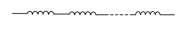
Symbols for Inductors
Like many other electronic components, the symbol for an inductor is a simplified pictogram of what it actually looks like:
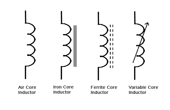
The lines near the symbol represent the core material – something we will discuss later.
Working of an Inductor
An inductor, as already mentioned, is just a coil of wire.
Before we go into anything else, let’s ask the question, why a coil?
As we already know, any current carrying conductor generates a magnetic field in the following fashion:
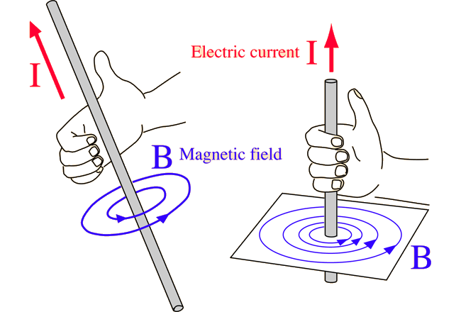
However, if you plug in the value of the current into the formulas, then you’ll realize that the magnetic field produced is tiny – almost negligible, unless the currents are impossibly high, in the order of mega-amps.
So in order to increase the magnetic field created by a specific length of wire, we wrap it into the form of a coil. This increases the magnetic field, like so:
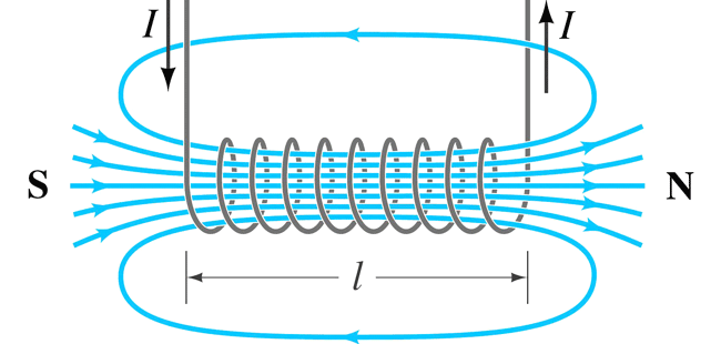
This shape is also called a solenoid.
When a voltage is applied across the terminals of an inductor, the current flowing creates a magnetic field. This magnetic field again creates an induced current in the inductor of opposite polarity, according to Lenz’s law. The currents do not cancel each other out – rather, the induced current actively tries to oppose the incoming current due to the voltage across the inductor. The overall result of this battle is that the current through an inductor cannot change rapidly – it is always a linear slope.
Measuring an Inductor
The working behavior of an inductor poses an interesting question – how do we quantitatively measure the behavior of an inductor in terms that is easily measurable?
We could try measuring inductors by the magnetic field that they create. As soon as we do that, we run into problems. The magnetic field created by an inductor depends on the current that passes through it, so even a small inductor can create a large magnetic field.
Instead, we could use the same approach we used for capacitors, and we can define inductance of a circuit as the voltage change induced when the current changes at a certain rate.
Mathematically,
V = L(dI/dt)
Where V is the voltage, L is the inductance, I is the current and t is the time period.
Inductance, ‘L’, is measured in Henrys, named after Joseph Henry, the American scientist who discovered electromagnetic induction.
The formula for calculating the inductance of a coil of wire is given by this formula:
L =(µn2a)/l
Where L is the inductance in Henrys, µ is the permeability constant, i.e. a coefficient of how easily the magnetic field can be created in a given medium, n is the number of turns, a is the area of the coil and l is the length of the coil.
Again, the Henry is a very large unit, so practically inductors are measured in microHenrys, uH, which is a millionth of a Henry, or milliHenrys, mH, which is a thousandth of a Henry. Occasionally you might even find very small inductances measured in nanoHenrys, which are a thousandth of a uH.
Different Types of Inductors
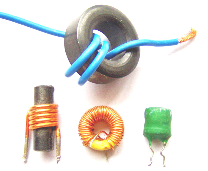
Now the µ in the above equation has some interesting implications. It suggests that the magnetic field inside the inductor can be manipulated. Like mentioned above, sometimes the magnetic field created even by a solenoid falls short of requirements sometimes. That is why in almost all cases you find inductors formed around a core material.
Cores are materials that support the creation of a magnetic field. They are generally made of iron and its compounds, such as ferrite (which is an oxide of iron). You can get a greater magnetic field using a core than without one.
1. AIR CORE INDUCTORS:
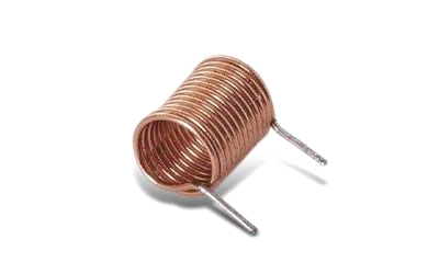
Like the name suggests, this kind of inductor has no core – the core material is air! Since air has a relatively low permeability, the inductance of air core inductors is quite low – rarely above 5uH. Since they have a low inductance, the rate of current rise is quite fast for an applied voltage and that makes them capable of handling high frequencies. They are mostly used in RF circuits.
2. IRON CORE INDUCTORS
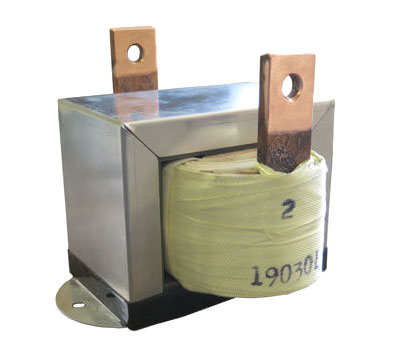
Iron is perhaps the most recognizable magnetic material, which makes it an ideal choice for inductors. These take the form of iron-core inductors. They are usually used for low frequency line filtering, since they can be rather beefy and have large inductances. They are also used in audio equipment.
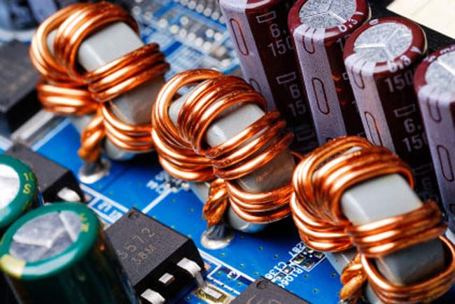
3. FERRITE CORE INDUCTORS
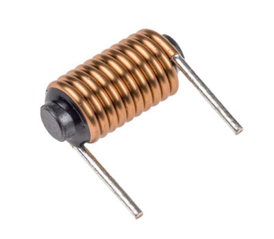
Ferrite is just a powder of oxides of iron. This powder is mixed with an epoxy resin and molded to form cores around which wires can be wound. Ferrite core inductors are easily the most recognizable because of their dull grey-black colour. They also are very brittle and break easily. They are the most widely used kinds of inductors, since the permeability can be finely controlled by controlling the ratio of ferrite to epoxy in the mix.
Inductors in Series and Parallel
Inductors connected in series and parallel behave the exact opposite way to capacitors.
For example, to calculate the inductance of a group of inductors in series, you can simply sum up the values of the individual inductances.
L = L1 + L2 + … + Ln
Where L is the total inductance and L1, L2…Ln are the individual inductances.
Suppose you have two inductors, one measuring 10uH and the other 15uH, then by putting them in series you obtain a total inductance of 25uH.
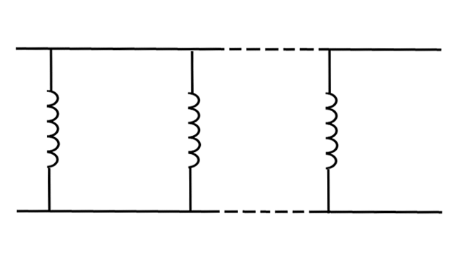
Inductors in parallel behave the same way as resistors in parallel, the inductance is given by:
1/L = 1/L1 + 1/L2 + … + 1/Ln
Where L is the total inductance and L1, L2…Ln are the individual inductances.
In this way if you connect two 10uH inductors in parallel, you’ll end up with an inductance of 5uH.
Useful Inductor Formulas
1. ENERGY STORED BY INDUCTORS:
Inductors can store energy much like capacitors, but the energy is gone the moment you disconnect the power and the magnetic field collapses. In other words, an unpowered inductor cannot sustain its magnetic field.
E = ½* L * I2
Where E is the energy in Joules, L is the inductance in Henries and I is the current in amps.
If you have an inductor of 20uH with a 5A current flowing through it, then the energy stored will be 0.00025J. In this aspect inductors too, like capacitors, hold very little energy.
2. RATE OF CURRENT RISE
This formula has already been discussed, but it is worth having a closer look.
V/L = dI/dt
Where V is the voltage applied across the inductor, L is the inductance, I is the current and t is the time.
This states that when a constant voltage is applied across the inductor, the current rises in a linear slope. This can be useful in creating current ramps, just like the capacitor created voltage ramps at a constant current.
3. IMPEDANCE
Inductors have impedance that is related to the frequency by the formula:
XL = 2π * f * L
Where XL is the inductive impedance, f is the frequency in Hertz and L is the inductance in Henrys.
Inductor Behavior in Circuits
Surprisingly, inductors are pretty much useless in DC circuits, since there is a constant current flowing and the inductor acts like a bit of wire.
They find most of their uses in AC circuits. Like mentioned above, they have an impedance, which makes them useful to limit current in an AC circuit, such as fluorescent lamp ballasts.
They can also be used to filter signals.
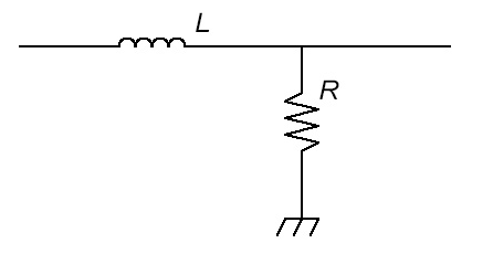
In the first case, the inductor allows all DC current to flow through it to ground, preventing all the low frequencies from reaching the output. At higher frequencies, the impedance of the inductor increases steadily, so the signal can pass through to the output, hence it is called a high pass filter.
In the second case, the inductor allows DC and low frequencies to pass through but blocks all high frequencies from the output and so it is called a low pass filter.
Inductors in Real Life
Inductors, since they are made of copper wire and ferrite, tend to be expensive and find most of their uses in radios, power supplies and telecoms equipment.
In power supplies, the property of an inductor to prevent sudden changes in current is used. Along with a capacitor, it acts to prevent sudden changes in the power supply output voltage and current.
RF circuits make use of an interesting LC circuit called a tank. The capacitor is charged and discharged into the inductor, which builds up its magnetic field. When the magnetic field collapses, a voltage is created and charges the capacitor. This creates periodic oscillations which can be used to generate high frequencies.
The frequency can be calculated by the formula:
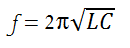
Where f is the frequency in Hertz, L is the inductance in Henrys and C is the capacitance in Farads.
Conclusion
And that is all the practical knowledge you will require to work with inductors. They are intrinsically simple devices and are not as prevalent as their capacitor and resistor relatives, but are still very useful.


