5V 5-Pin Relay
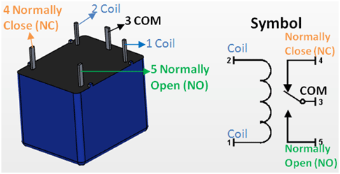
Relay Pin Configuration
|
Pin Number |
Pin Name |
Description |
|
1 |
Coil End 1 |
Used to trigger(On/Off) the Relay, Normally one end is connected to 5V and the other end to ground |
|
2 |
Coil End 2 |
Used to trigger(On/Off) the Relay, Normally one end is connected to 5V and the other end to ground |
|
3 |
Common (COM) |
Common is connected to one End of the Load that is to be controlled |
|
4 |
Normally Close (NC) |
The other end of the load is either connected to NO or NC. If connected to NC the load remains connected before trigger |
|
5 |
Normally Open (NO) |
The other end of the load is either connected to NO or NC. If connected to NO the load remains disconnected before trigger |
Features of 5-Pin 5V Relay
- Trigger Voltage (Voltage across coil) : 5V DC
- Trigger Current (Nominal current) : 70mA
- Maximum AC load current: 10A @ 250/125V AC
- Maximum DC load current: 10A @ 30/28V DC
- Compact 5-pin configuration with plastic moulding
- Operating time: 10msec Release time: 5msec
- Maximum switching: 300 operating/minute (mechanically)
Equivalent Relays
3V Relay, 12V Relay, 1-channel Relay module, 4-channel Relay Module.
How to use a Relay
Relays are most commonly used switching device in electronics. Let us learn how to use one in our circuits based on the requirement of our project.
Before we proceed with the circuit to drive the relay we have to consider two important parameter of the relay. Once is the Trigger Voltage, this is the voltage required to turn on the relay that is to change the contact from Common->NC to Common->NO. Our relay here has 5V trigger voltage, but you can also find relays of values 3V, 6V and even 12V so select one based on the available voltage in your project. The other parameter is your Load Voltage & Current, this is the amount of voltage or current that the NC,NO or Common terminal of the relay could withstand, in our case for DC it is maximum of 30V and 10A. Make sure the load you are using falls into this range.
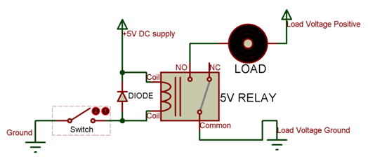
The above circuit shows a bare-minimum concept for a relay to operate. Since the relay has 5V trigger voltage we have used a +5V DC supply to one end of the coil and the other end to ground through a switch. This switch can be anything from a small transistor to a microcontroller or a microprocessor which can perform switching operating. You can also notice a diode connected across the coil of the relay, this diode is called the Fly back Diode. The purpose of the diode is to protect the switch from high voltage spike that can produced by the relay coil. As shown one end of the load can be connected to the Common pin and the other end is either connected to NO or NC. If connected to NO the load remains disconnected before trigger and if connected to NC the load remains connected before trigger.
Applications of Relay
- Commonly used in switching circuits.
- For Home Automation projects to switch AC loads
- To Control (On/Off) Heavy loads at a pre-determined time/condition
- Used in safety circuits to disconnect the load from supply in event of failure
- Used in Automobiles electronics for controlling indicators glass motors etc.
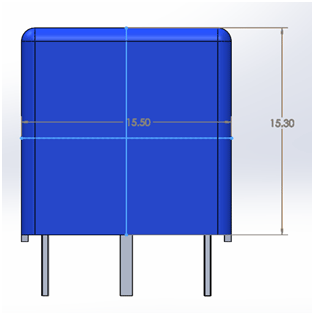
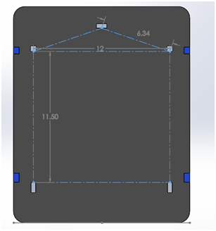
2D model of the Relay