

Optimized with highly sensitive cap touch sensors, extensive peripheral circuits and 125℃ operation
Introduction to Transformers
If you’ve been around electric appliances for any amount of time, you’d probably have heard of the transformer. Yes, they are those huge bulky things found in street corners, which make random scary noises and occasionally spit sparks. Your phone charger also has a kind of small transformer too, but much, much smaller and with a completely different mechanism.
What is a Transformer?
A transformer is a device that uses the principles of electromagnetism to convert one voltage or current to another. It consists of a pair of insulated wires wound around a magnetic core. The winding to which we connect the voltage or current to be converted is called the primary winding and the output winding is called the secondary winding.
There are many types of transformed, but for a simplified explanation we can assume that transformers come in two varieties – step up, which increases the voltage or current, and steps down, which decreases the voltage or current input. For example, the transformer in your microwave Oven is a secondary transformer that is used to supply around 2200Volts to the vacuum tube in the Microwave Oven.
One thing to note is that transformers work only with changing or AC voltages and do not work with DC. We shall now learn why.
How important are transformers in the electrical system?
It was around 1856 when two brilliant minds Nikola Tesla and Thomas Edison were having a rivalry against each other. Those were the times when electricity and its applications of glowing a bulb and running a motor were just being noticed. It was Edison and his associates who first discovered DC (Direct Current) system, then sometime after that Tesla came up with his AC (Alternating current) system. Since then, both were trying to prove that their system is more advantageous than the other.
By then, the time has come for houses to get electricity. While Edison was busy demonstrating how dangerous AC is by electrocuting elephants, Tesla and his team came up with the transformers which made transmitting electricity a lot easier and more efficient. Even, today Transformers play a vital role in the transmission system. Let’s know why.
Transmitting electricity with high voltages and low currents will help us reduce the thickness of the transmission wires and thus the cost, it also increases the efficiency of the system. For this reason, a standard transmission system can be anywhere between 22KV to 66KV, while some generators in the power plant has an output voltage of only 11kV, and the household AC appliance requires only 220V/110V. So where does this voltage conversion take place and who does it.
The answer to the question is transformers. From the power plant to your home there will be transformers in the system that will either step-up (increase voltage) or step-down (decrease voltage) the voltage to maintain the efficiency of the system. This is why the transformers are called the heart of an electrical transmission system. We will learn more about them in this article.
Transformer Symbols
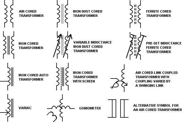
The circuit symbol for a transformer is simply two inductors put together side by side sharing the same core. The nature of the line in between the two windings indicates the type of core used: A dashed line represents ferrite, two parallel lines represent laminated iron and no line represents air core.
Sometimes the number of ‘bumps’ is used as a rough indicator of the transformer function – less bumps on one side and more on the other may mean that the first side has a smaller number of turns than the other.
How Does a Transformer Work?
To understand the working of a transformer, we need to go back in time, to Michael Faraday’s laboratory.
Michael Faraday can perhaps be called the father of the transformer since it was his experiments that helped us understand electromagnetism and develop devices like motors and generators.
In the late 1800s, when it was discovered that electricity and magnetism were related phenomena, there was a race to try and build a practical device that could harness the power of magnets to generate electricity.
Faraday found out that electricity could be generated by bringing a magnet close to a coil of wire. What he discovered was that voltage will be produced only when the magnetic field was changing, that is, if he moved either the coil or the magnet relative to the other.
In DC, the current flow is steady and so is the magnetic field. Since the field is steady and not changing, there is no voltage induced on the secondary and the transformer just looks like a normal coil of resistive wire to the power supply. So transformers do not work with DC currents.
He also found that when two coils of wire were kept close to each other, a current flowing in one coil could induce a current in the other coil. This principle is called mutual inductance and governs the working of all modern transformers.
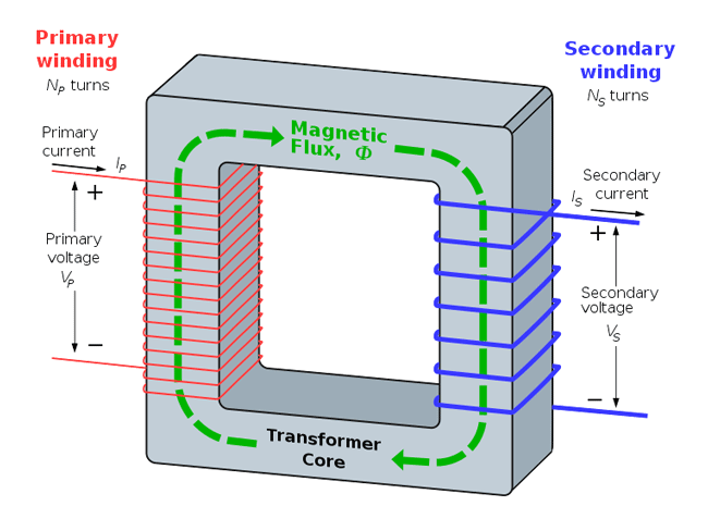
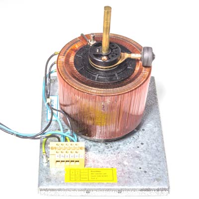
As shown in the figure, the transformer consists of two windings wound on a magnetic core.
The purpose of having a core is because air is not a very good supporter of magnetic fields, so having a magnetic core increases the magnetic field for a given amount of current flowing through one winding, which in turn creates a stronger current in the other, increasing the overall efficiency of the device.
When a current passes through the primary, a magnetic field is set up in the core and is confined mostly to the core.
This magnetic field passes through the middle of the secondary and hence induces a current in the other by the law of mutual induction.
The beauty of this system is that the ratio of the input voltage to the output voltage is simply the ratio of the primary and the secondary windings, summed up by this formula:
Vout/Vin = Nsec/Npri
Where Vout is the output voltage, Vin is the input voltage, Nsec is the number of turns in the secondary winding and Npri is the number of turns in the primary winding.
So if you have two transformers, one with 100 turns on the primary and 1000 on the secondary and another with 10 turns on the primary and 100 turns on the secondary, you can calculate the turns ratio to be 1:10 for both, so they both step up voltage to the same level.
Transformer Properties
If we have a closer look at the example given above, the first transformer will have a greater winding resistance (since more wire is used) and in some cases that might limit the amount of current that can be drawn from the transformer. This property is called winding resistance, but in most cases it does not really matter since the copper wire used generally has a low resistance.
Another thing you notice is that there is no direct electrical connection between the primary and secondary windings. This is called galvanic isolation, and can be very useful, as we shall see.
Looking at each of the transformer windings, we can see that they are constructed just like inductors – a coil of wire wound around a magnetic core – and have an inductance too.
This inductance is proportional to the square of the number of turns, given by this formula:
Lpri/Lsec = Npri2/Nsec2
Where Lpri is the inductance of the primary winding, Lsec is the inductance of the secondary winding, Npri is the number of turns on the primary and Nsec is the number of turns on the secondary windings.
The proportionality constant for a given core can be found in the datasheet and is usually given in units of µH/turn2. The exact value depends on the type and size of core.
Supposing you have a transformer core with a specification of 1uH/turn2. If you wind one winding on that core, then the inductance will be the value of the constant multiplied by the number of turns squared, in this case 1. So the inductance of that one winding will be 1µH. If you wind another winding with 10 turns on the same core, then the inductance will be:
(1µH/turn2)*(10 turns)2 = 100µH
Since the windings have inductance, they provide an impedance to AC signals, given by the formula:
XL = 2π*f*L
Where XL is the impedance in ohms, f is the frequency in ohms and L is the inductance in Henries.
Say you want to design a transformer that draws 3A at 220V AC at 50Hz, which is standard power line frequency. Then the impedance of the primary would need to be 73.3 Ohms by Ohm’s law. Now that we know the impedance required and the frequency, we can rearrange the formula to find out the inductance necessary for the winding:
L = (XL)/(2π*f)
Substituting the values, we find that the inductance needed would be 233mH.
Using this information and the value of µH/turns2 from the datasheet, we can calculate the windings required to get the inductance required.
Supposing that value is 50µH/turns2, then we can rearrange the formula to find out the inductance:
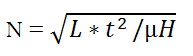
Where N is the number of turns, L is the required inductance, and the t2/µH term is just the inverse of the datasheet value.
Applying our values in the formula, we get a required number of turns of 2158. So as you can see, one you get the hang of the formulas, you can design transformers for nearly any application!
Transformer Construction
For anyone who needs to wind their own transformers, a knowledge of transformer construction is essential.
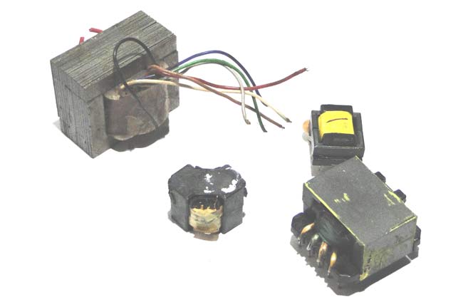
A transformer consists of a few basic components, below are the transformer parts:
1. BOBBIN:
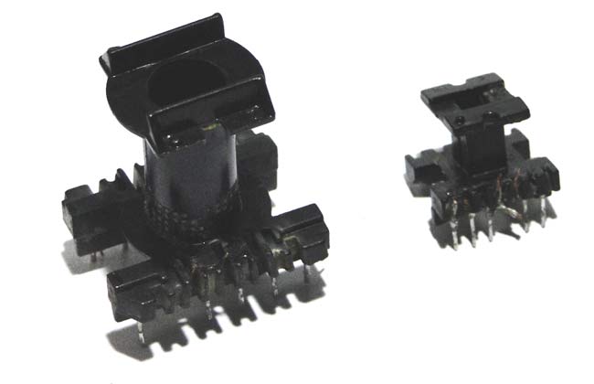
The bobbin is the basic framework for any transformers. It provides a spool on which to wind the windings and also holds the core in place. It is usually made up of a heat resistant plastic. It also sometimes contains metal pins onto which you can solder the ends of the windings if you want to mount it to a PCB, for instance.
2. CORE
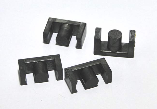
This is probably the most important part of the transformer. As shown in the picture, the cores can come in many shapes and sizes. It is the magnetic properties of the core that determine the electrical properties of the transformer which is built around the core.
3. WINDINGS
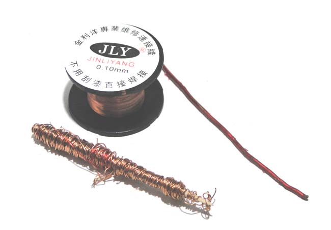
Thought it may seem like a trivial thing, the wire used in the construction is as important as any other aspect. Solid enameled copper wire is generally used, since the insulation is strong and thin, so no wasted space due to plastic insulating sheaths. You can check out our article on how to design and build SMPS transformer if you want more information to build your own transformer.
Application of Transformers
1. MAINS VOLTAGE CONVERSION
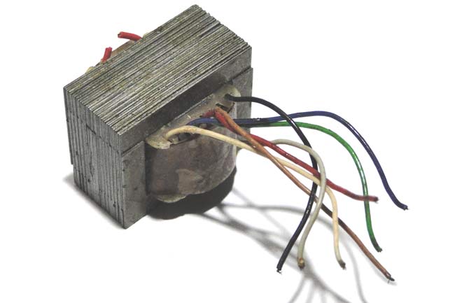
This is probably the most common application for transformers – stepping down mains voltage for low voltage appliances. You might even find these inside things like microwaves and old TVs and wall brick power supplies. These transformers have iron cores which gives excellent permeability but makes them bulky and somewhat less powerful than other types.
They are marked like 12-0-12 or 6-0-6 with three secondary wires. This means that the outer two wires have an output of 12V AC RMS if you make the center wire the ground reference. If you measure across both the 12v winding, you will get 24V AC RMS. This gives you flexibility on how you might want to use the transformer.
2. SWITCH MODE POWER SUPPLIES
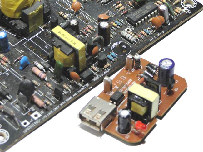
These are a very special type of power supplies that take a DC input and produce a DC output. They are found all modern phone chargers. The transformers used in these PSUs are designed more like inductors with a small number of turns and ferrite cores with medium-to-high permeability. A DC voltage is applied across the ‘primary’ for a short time so that the current ramps up to a certain level and stores some magnetic energy in the core. This energy is then transferred to the secondary at a lower voltage because it has a smaller number of turns. They operate at high frequencies and achieve excellent efficiencies and are very small.
3. ELECTRICAL ISOLATION
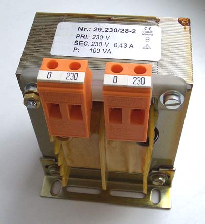
These are special transformers with a 1:1 turns ratio, so that the input and output voltages are the same. They are used to decouple appliances from mains earth. Since mains is earth referenced, touching even one wire can result in a shock since the return path is literally the ground. Using isolation transformers ‘disconnects’ the appliance from the mains earth, since transformers are galvanically isolated.
4. VOLTAGE CONVERSION TRANSFORMERS
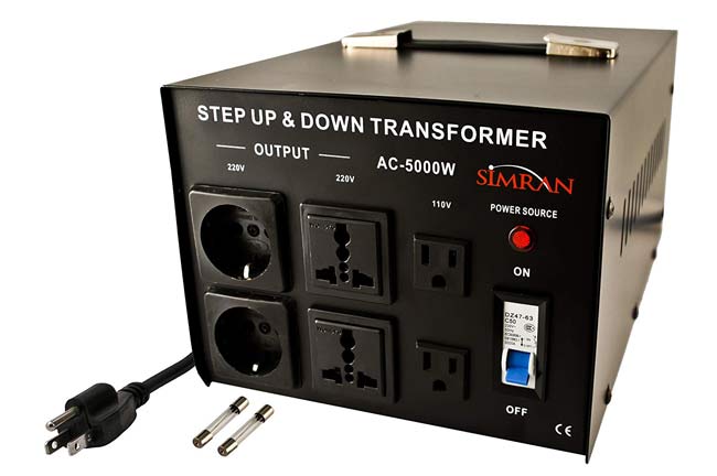
Most countries around the world use 220V AC as the standard supply voltage, but some countries like the US use 110V AC. This means that some devices like blenders cannot be operated in all countries. For this purpose we can use transformers that convert 110V to 220V or vice versa to make sure that appliances can be used in any country.
5. IMPEDANCE MATCHING
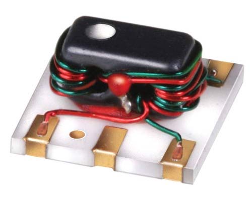
These are special kinds of transformers that are used to match the impedance of the source and the load. They see extensive use in RF and audio circuits.
The turns ratio is equal to the square root of the source and load impedances.
6. AUTOTRANSFORMER
This is a special type of transformer that has only one winding with a ‘tap’ output that forms the secondary. Usually this tap is variable, and so you can vary the output AC voltage, somewhat like a voltage divider.
Conclusion
Transformers are useful devices and learning how to design and work with them can come in very handy! While we have covered the basics here, designing a transformer right from scratch is something that can discussed in another entire article hence lets have that for some other time. So now, when you see a transformer again you will know why it is there and how it works.


