Arduino Nano
The Arduino Nano is another popular Arduino development board very much similar to the Arduino UNO. They use the same Processor (Atmega328p) and hence they both can share the same program.
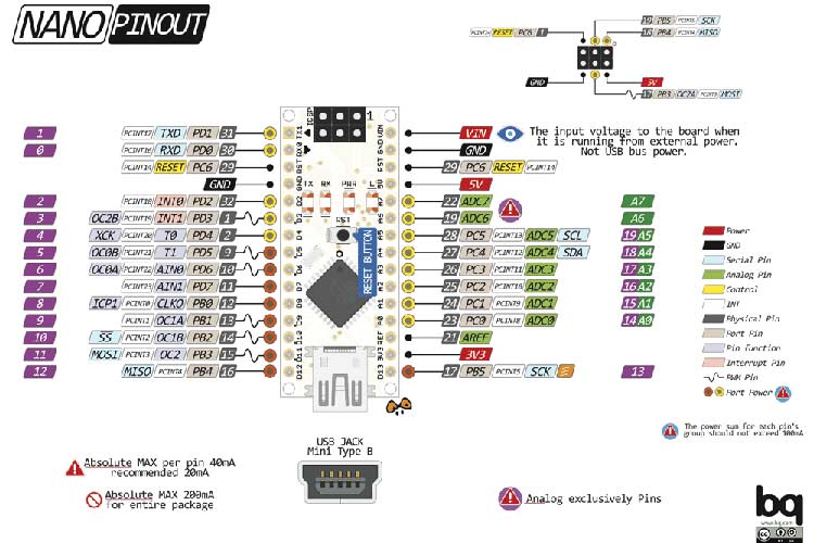
Arduino Nano Pinout Configuration
|
Pin Category |
Pin Name |
Details |
|
Power |
Vin, 3.3V, 5V, GND |
Vin: Input voltage to Arduino when using an external power source (6-12V). 5V: Regulated power supply used to power microcontroller and other components on the board. 3.3V: 3.3V supply generated by on-board voltage regulator. Maximum current draw is 50mA. GND: Ground pins. |
|
Reset |
Reset |
Resets the microcontroller. |
|
Analog Pins |
A0 – A7 |
Used to measure analog voltage in the range of 0-5V |
|
Input/Output Pins |
Digital Pins D0 - D13 |
Can be used as input or output pins. 0V (low) and 5V (high) |
|
Serial |
Rx, Tx |
Used to receive and transmit TTL serial data. |
|
External Interrupts |
2, 3 |
To trigger an interrupt. |
|
PWM |
3, 5, 6, 9, 11 |
Provides 8-bit PWM output. |
|
SPI |
10 (SS), 11 (MOSI), 12 (MISO) and 13 (SCK) |
Used for SPI communication. |
|
Inbuilt LED |
13 |
To turn on the inbuilt LED. |
|
IIC |
A4 (SDA), A5 (SCA) |
Used for TWI communication. |
|
AREF |
AREF |
To provide a reference voltage for input voltage. |
Arduino Nano Technical Specifications
|
Microcontroller |
ATmega328P – 8-bit AVR family microcontroller |
|
Operating Voltage |
5V |
|
Recommended Input Voltage for Vin pin |
7-12V |
|
Analog Input Pins |
6 (A0 – A5) |
|
Digital I/O Pins |
14 (Out of which 6 provide PWM output) |
|
DC Current on I/O Pins |
40 mA |
|
DC Current on 3.3V Pin |
50 mA |
|
Flash Memory |
32 KB (2 KB is used for Bootloader) |
|
SRAM |
2 KB |
|
EEPROM |
1 KB |
|
Frequency (Clock Speed) |
16 MHz |
|
Communication |
IIC, SPI, USART |
Other Arduino Boards
Arduino UNO, Arduino Pro Mini, Arduino Mega, Arduino Due, Arduino MKR1000 Wi-Fi Board, Arduino Leonardo
Other Development Boards
Raspberry Pi, PIC Development Board, AVR Development Board, MSP430 Launchpad, TEENSY 3.6 Development Board, Intel Edison, ESP32, STM32F103C8T6 - Blue Pill Development Board, NodeMCU ESP8266
Difference between Arduino UNO and Arduino Nano
The Arduino Nano is very much similar to the Arduino UNO. They use the same Processor (Atmega328p) and hence they both can share the same program. One big difference between both is the size. UNO is twice as big as Nano and hence occupies more space on your project. Also, Nano is breadboard friendly while Uno is not. To program an Uno, you need a Regular USB cable; whereas for Nano, you will need a mini USB cable. The technical difference between Uno and Nano is shown below:
|
Name |
Processor |
Operating/Input Voltage |
CPU speed |
Analog In/Out |
Digital IO/PWM |
EEPROM / SRAM[kB] |
Flash |
USB |
USART |
|
Uno |
ATmega328P |
5V / 7-12V |
16 MHz |
6 / 0 |
14 / 6 |
1 / 2 |
32 |
Regular |
1 |
|
Nano |
ATmega328P |
5V / 7-12V |
16 MHz |
8 / 0 |
14 / 6 |
1 / 2 |
32 |
Mini |
1 |
Difference between Arduino Nano and Arduino Mega
There is a considerable amount of difference between the Arduino Nano and the Arduino mega as the processor used itself is different. Arduino Mega is more powerful than an Arduino Nano in terms of speed and number of I/O pins. As you might guess, the size is also bigger than an Arduino UNO. Arduino Mega is normally used for projects which require a lot of I/O pins and different communication protocols. The technical difference between Nano and Mega is shown below.
|
Name |
Processor |
Operating/Input Voltage |
CPU speed |
Analog In/Out |
Digital IO/PWM |
EEPROM / SRAM[kB] |
Flash |
USB |
USART |
|
Mega |
5V / 7-12V |
16 MHz |
16 / 0 |
54 / 15 |
4 / 8 |
256 |
Regular |
4 |
|
|
Nano |
ATmega328P |
5V / 7-12V |
16 MHz |
8 / 0 |
14 / 6 |
1 / 2 |
32 |
Mini |
1 |
Understanding Arduino Nano
The Arduino board is designed in such a way that it is very easy for beginners to get started with microcontrollers. This board especially is breadboard friendly, and that's why it is very easy to handle the connections. Let’s start with powering the Board.
Powering you Arduino Nano:
There are total three ways by which you can power your Nano.
USB Jack: Connect the mini USB jack to a phone charger or computer through a cable and it will draw power required for the board to function
Vin Pin: The Vin pin can be supplied with an unregulated 6-12V to power the board. The on-board voltage regulator regulates it to +5V.
+5V Pin: If you have a regulated +5V supply then you can directly provide this o the +5V pin of the Arduino.
Input/output:
There are total 14 digital Pins and 8 Analog pins on your Nano board. The digital pins can be used to interface sensors by using them as input pins or drive loads by using them as output pins. A simple function like pinMode() and digitalWrite() can be used to control their operation. The operating voltage is 0V and 5V for digital pins. The analog pins can measure analog voltage from 0V to 5V using any of the 8 Analog pins using a simple function like analogRead().
These pins apart from serving their purpose, can also be used for special purposes, which are discussed below:
- Serial Pins 0 (Rx) and 1 (Tx): Rx and Tx pins are used to receive and transmit TTL serial data. They are connected with the corresponding ATmega328P USB to TTL serial chip.
- External Interrupt Pins 2 and 3: These pins can be configured to trigger an interrupt on a low value, a rising or falling edge, or a change in value.
- PWM Pins 3, 5, 6, 9 and 11: These pins provide an 8-bit PWM output by using analogWrite() function.
- SPI Pins 10 (SS), 11 (MOSI), 12 (MISO) and 13 (SCK): These pins are used for SPI communication.
- In-built LED Pin 13: This pin is connected with a built-in LED. When pin 13 is HIGH – LED is on and when pin 13 is LOW, it is off.
- I2C A4 (SDA) and A5 (SCA): Used for IIC communication using Wire library.
- AREF: Used to provide reference voltage for analog inputs with analogReference() function.
- Reset Pin: Making this pin LOW, resets the microcontroller.
These special functions and their respective pins are illustrated in the Arduino Nano pinout diagram shown above.
How to use Arduino Nano
It will hardly take 5-10 minutes to upload your first program to Arduino Nano. All you need the Arduino IDE, an USB cable and your Nano board itself.
Download and Install Arduino:
The first step would be to install the Arduino IDE which is available for download for free from the below link. After installing Arduino, you might also want to install the drivers (link given below) for your Arduino to communicate with your Computer.
Uploading your first program
Once arduino IDE is installed on the computer, connect the board with computer using USB cable. Now open the arduino IDE and choose the correct board by selecting Tools>Boards>Arduino/Nano, and choose the correct Port by selecting Tools>Port. Arduino Uno is programmed using Arduino programming language based on Wiring. To get it started with Arduino Uno board and blink the built-in LED, load the example code by selecting Files>Examples>Basics>Blink. Once the example code (also shown below) is loaded into your IDE, click on the ‘upload’ button given on the top bar. Once the upload is finished, you should see the Arduino’s built-in LED blinking. Below is the example code for blinking:
// the setup function runs once when you press reset or power the board
void setup() {
  // initialize digital pin LED_BUILTIN as an output.
  pinMode(LED_BUILTIN, OUTPUT);
}
// the loop function runs over and over again forever
void loop() {
  digitalWrite(LED_BUILTIN, HIGH);   // turn the LED on (HIGH is the voltage level)
  delay(1000);                       // wait for a second
  digitalWrite(LED_BUILTIN, LOW);    // turn the LED off by making the voltage LOW
  delay(1000);                       // wait for a second
}
Applications
- Prototyping of Electronics Products and Systems
- Multiple DIY Arduino Projects.
- Easy to use for beginner-level DIYers and makers.
- Projects requiring Multiple I/O interfaces and communications.
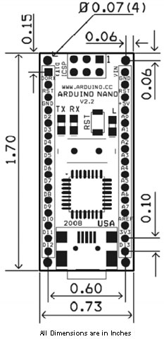
2D Model and Dimensions


