ESP32 - DevKitC
ESP32 DevKitC Pinout Configuration
|
Pin Category |
Pin Name |
Details |
|
Power |
Micro-USB, 3.3V, 5V, GND |
Micro-USB: ESP32 can be powered through USB port 5V: Regulated 5V can be supplied to this pin which is we be again regulated to 3.3V by on board regulator, to power the board. 3.3V: Regulated 3.3V can be supplied to this pin to power the board. GND: Ground pins. |
|
Enable |
En |
The pin and the button resets the microcontroller. |
|
Analog Pins |
ADC1_0 to ADC1_5 and ADC2_0 to ADC2_9 |
Used to measure analog voltage in the range of 0-3.3V. 12-bit 18 Channel ADC |
|
DAC pins |
DAC1 and DAC2 |
Used for Digital to analog Conversion |
|
Input/Output Pins |
GPIO0 to GPIO39 |
Totally 39 GPIO pins, can be used as input or output pins. 0V (low) and 3.3V (high). But pins 34 to 39 can be used as input only |
|
Capacitive Touch pins |
T0 to T9 |
These 10 pins can be used as touch pins normally used for capacitive pads |
|
RTC GPIO pins |
RTCIO0 to RTCIO17 |
These 18 GPIO pins can be used to wake up the ESP32 from deep sleep mode. |
|
Serial |
Rx, Tx |
Used to receive and transmit TTL serial data. |
|
External Interrupts |
All GPIO |
Any GPIO can be used to trigger an interrupt. |
|
PWM |
All GPIO |
16 independent channel is available for PWM any GPIO can be made to work as PWM through the software |
|
VSPI |
GPIO23 (MOSI), GPIO19(MISO), GPIO18(CLK) and GPIO5 (CS) |
Used for SPI-1 communication. |
|
HSPI |
GPIO13 (MOSI), GPIO12(MISO), GPIO14(CLK) and GPIO15 (CS) |
Used for SPI-2 communication. |
|
IIC |
GPIO21(SDA), GPIO22(SCL) |
Used for I2C communication. |
|
AREF |
AREF |
To provide a reference voltage for input voltage. |
ESP32 Technical Specifications
|
Microprocessor |
Tensilica Xtensa LX6 |
|
Maximum Operating Frequency |
240MHz |
|
Operating Voltage |
3.3V |
|
Analog Input Pins |
12-bit, 18 Channel |
|
DAC Pins |
8-bit, 2 Channel |
|
Digital I/O Pins |
39 (of which 34 is normal GPIO pin) |
|
DC Current on I/O Pins |
40 mA |
|
DC Current on 3.3V Pin |
50 mA |
|
SRAM |
520 KB |
|
Communication |
SPI(4), I2C(2), I2S(2), CAN, UART(3) |
|
Wi-Fi |
802.11 b/g/n |
|
Bluetooth |
V4.2 – Supports BLE and Classic Bluetooth |
Note: More technical information can be found in the ESP32 DevKitC Datasheet, linked at the bottom of this page.
Other Espressif Boards
Other Development Boards
Arduino, Raspberry Pi, PIC Development Board, AVR Development Board, MSP430 Launchpad, Intel Edison, Beagle Bone
ESP32 vs Arduino
It is completely unfair to compare ESP32 with Arduino; both are advantageous and functional on its own. In terms of power and features, obviously the dual cored microprocessor powered ESP32 will surely take down the microcontroller powered Arduino UNO. The ESP32 has built in Bluetooth and Wi-Fi with a good number of GPIO pins and communication protocols for a very cheap price. The Arduino might look a bit handicapped when competing with ESP32 but it has a large number of shields in the market which can be readily used, also advanced Arduino boards like Yun has good processing power as well.
The ESP32 operates on 3.3V and can be programmed with ESP-IDF or with Arduino IDE which is still under development; the Arduino operates at 5V and is known for its easy-to-use Arduino IDE and strong community support. So to conclude, if you have prior experience with programming and your project really requires some heavy processing with IoT capabilities, then ESP32 can be preferred over Arduino.
ESP32 vs ESP8266
Both the ESP32 and ESP8266 are Wi-Fi development boards from Espressif systems. They can be programmed using the ESP-IDF or the Arduino IDE. The ESP8266 is inferior in terms of performance compared with the ESP32, but it is cheaper and has a smaller form factor than the ESP32. Also, the ESP8266 was launched into the market earlier than ESP32, so you will get enough community support for ESP8266.
The main difference would be that ESP8266 does not have an in-built Bluetooth module and also does not feature CAN protocol and has no SRAM. So if your project requires more processing power with Bluetooth or CAN functionalities then you can prefer ESP32 over ESP8266.
|
Name |
Processor |
GPIO pins |
CPU speed |
Analog In |
Bluetooth |
CAN |
SRAM |
USB |
SPI/I2C/I2S/UART |
|
ESP8266 |
Xtensa Single-core 32-bit L106 |
17 |
80 MHz |
10 bit |
No |
No |
No |
Mini |
2/1/2/2 |
|
ESP32 |
Xtensa Dual-Core 32-bit LX6 with 600 DMIPS |
36 |
160 MHz |
12-bit |
Yes |
Yes |
Yes |
Mini |
4/2/2/2 |
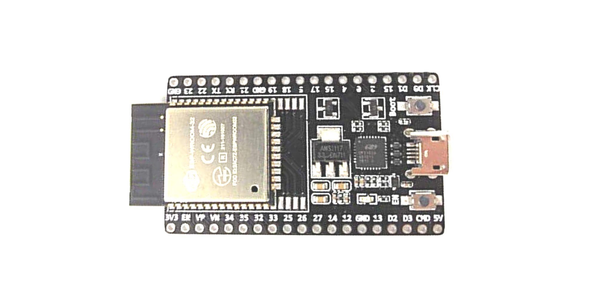
Understanding ESP32 Board
The ESP32 is design for low power IoT applications in mind. It’s high processing power with in-built Wi-Fi / Bluetooth and Deep Sleep Operating capabilities makes it ideal for most Portable IoT devices. Also now, since Arduino IDE has officially released board managers for ESP32, it has become very easy to program these devices.
Powering your ESP32
There are total three ways by which you can power your ESP32 board-
Micro USB Jack: Connect the mini USB jack to a phone charger or computer through a cable and it will draw power required for the board to function
5V Pin: The 5V pin can be supplied with a Regulated 5V, this voltage will again be regulated to 3.3V through the on-board voltage regulator. Remember ESP32 operated with 3.3V only.
3.3V Pin: If you have a regulated 3.3V supply, then you can directly provide this to the 3.3V pin of the ESP32.
Input/output
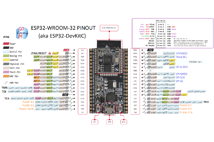
There are totally 39 digital Pins on the ESP32 out of which 34 can be used as GPIO and the remaining are input only pins. The device supports 18-channels for 12-bit ADC and 2-channel for 8-bit DAC. It also has 16 channels for PWM signal generation and 10 GPIO pins supports capacitive touch features. The ESP32 has multiplexing feature, this enables the programmer to configure any GPIO pin for PWM or other serial communication through program. The ESP32 supports 3 SPI Interface, 3 UART interface, 2 I2C interface, 2 I2S interface and also supports CAN protocol.
- 3 UART interface: The ESP32 supports 3 UART interface for TTL communication. This would require 3 sets of Rx and Tx pins. All the 6 pins are software configurable and hence any GPIO pin can be programmed to be used for UART.
- External Interrupt: Again since the ESP32 supports multiplexing any GPIO pin can be programmed to be used as an interrupt pin.
- GPIO23 (MOSI), GPIO19(MISO), GPIO18(CLK) and GPIO5 (CS): These pins are used for SPI communication. ESP32 supports two SPI, this is the first set.
- GPIO13 (MOSI), GPIO12(MISO), GPIO14(CLK) and GPIO15 (CS): These pins are used for SPI communication. ESP32 supports two SPI, this is the second set.
- GPIO21(SDA), GPIO22(SCL): Used for IIC communication using Wire library.
- Reset Pin: The reset pin for ESP32 is the Enable (EN) pin. Making this pin LOW, resets the microcontroller.
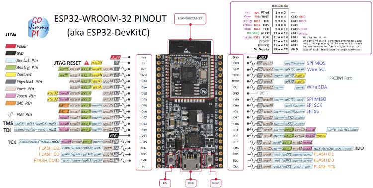
These special functions and their respective pins are illustrated in the below picture-
How to use ESP32
The native platform to program ESP32 is the ESP-IDF, but most beginners use Arduino IDE since it is easy to use. If you want to work with the native platform, you can check the official Starter guide from Espressif itself.
If you are using the Arduino IDE, it will hardly take 5-10 minutes to upload your first program to ESP32. All you need the Arduino IDE, an USB cable, and ESP32 board itself. You can check this Arduino ESP32 guide to prepare your Arduino for ESP32.
Uploading your first program
Once arduino IDE is installed on the computer, connect the board with computer using USB cable. Now open the arduino IDE and choose the correct board by selecting Tools>Boards>ESP32 Dev kit, and choose the correct Port by selecting Tools>Port. To get it started with ESP32 board and blink the built-in LED, load the example code by selecting Files>Examples>Basics>Blink. Once the example code (also shown below) is loaded into your IDE, click on the ‘upload’ button given on the top bar. Once the upload is finished, you should see the ESP32’s built-in LED blinking. Below is the example code for blinking:
int LED_BUILTIN = 2;
void setup() {
pinMode (LED_BUILTIN, OUTPUT);
}
void loop() {
digitalWrite(LED_BUILTIN, HIGH);
delay(1000);
digitalWrite(LED_BUILTIN, LOW);
delay(1000);
}
Applications
- Prototyping of IoT devices
- Low power battery operated applications
- Network projects
- Easy to use for beginner level DIYers and makers.
- Projects requiring Multiple I/O interfaces with Wi-Fi and Bluetooth functionalities.
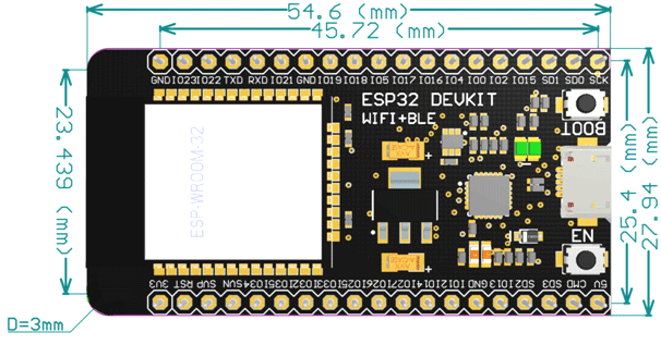
ESP32 2D Model