PAM8302- 2.5W Filterless Class-D Mono Audio Amplifier
The PAM8302A is a single-channel, filterless, cheap, Class-D audio amplifier IC. It offers high-quality sound reproduction. It is designed for portable and battery-powered audio applications due to its high efficiency and low power consumption. The filterless design eliminates the need for output filters, reducing the external component count and overall cost. The device operates from a single power supply ranging from 1.8V to 5.5V, making it suitable for use with a variety of power sources, including lithium-ion batteries. The high efficiency of the Class-D architecture ensures minimal power loss, which is suitable for portable applications where battery life is critical. The PAM8302 offers thermal shutdown and short-circuit protection. The PAM8302A is available in MSOP-8, SO-8, and U-DFN3030-8 (Type E) packages.
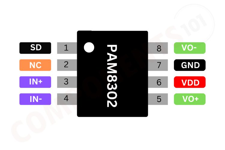
PAM8302 Pinout Configuration
Here are the pinout details for PAM8302.
| Pin Number | Pin Name | Function |
| 1 | SD | Shutdown control input |
| 2 | NC | No connection |
| 3 | IN+ | Positive differential audio input |
| 4 | IN- | Negative differential audio input |
| 5 | VO+ | Positive differential audio output |
| 6 | VDD | Power supply input |
| 7 | GND | ground |
| 8 | VO- | Negative differential audio output |
Features of PAM8302
PAM8302 amplifier has the following key features:
- 2.5W Output at 10% THD with a 4Ω Load and 5V Power Supply
- Filterless
- Low Quiescent Current and Low EMI
- High Efficiency up to 88%
- Superior Low Noise
- Short Circuit Protection
- Thermal Shutdown
- Few External Components to Save Space and Cost
- MSOP-8, SO-8 and U-DFN3030-8 (Type E) Packages Available
Manufacturers of PAM8302:
The PAM8302 is originally manufactured by Diodes INC.
PAM8302 Equivalents
There is no pin-to-pin compatible equivalent for PAM8302
PAM8302 Alternatives
If you are looking for an alternative for PAM8302 you can look at the other audio amplifier ICs from these. They may not have the same specifications, but they are some of the most popular audio amplifier ICS.
LM386, TDS7294, PAM8610, TDA1554, TDA2030, TDA7294, TDA7265, TDA7279, TDA2005, TDA2002, LM3886, LA4440
Note: Complete technical details can be found in the PAM8302 datasheet at this page’s end.
PAM8302 Schematics
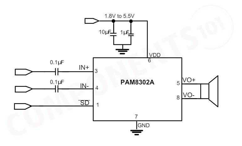
This circuit is a typical application circuit of the PAM8302 audio amplifier IC, designed for audio amplification.
The PAM8302A operates with a supply voltage (VDD) between 1.8V to 5.5V. The circuit includes two decoupling capacitors, a 10µF capacitor, and a 1µF capacitor connected in parallel between VDD and ground. These capacitors help to filter and stabilize the power supply. The audio input signals are connected to pins 3 (IN+) and 4 (IN-). Each input pin has a 0.1µF capacitor in series. These capacitors block any DC component in the input signal, allowing only the AC component (audio signal) to pass through to the amplifier. Pin 1 (SD) is the shutdown control pin. When this pin is pulled low, the amplifier is turned off, reducing power consumption. When pulled high, the amplifier operates normally. The output audio signal is taken from pins 5 (VO+) and 8 (VO-). These pins are connected directly to the speaker, which receives the amplified audio signal.
Troubleshooting Tips for PAM8302
There is no sound output from the amplifier, what could be the issue?
First Check all cable connections between the amplifier, source device (player, phone etc.), and speakers. Ensure they're securely plugged in. Verify the values of resistors. Try it with a different source device to isolate the problem. Check shutdown pin status, if it is not high pull, it too high.
Getting only Distorted Sound:
First, try lowering the volume. Clipping often happens at high volumes. Check speakers for any tears or damage in the cones. Damaged speakers can cause distortion.
My amplifier output is very Low:
Verify the speaker impedance matches the amplifier's specifications. Using speakers with a much higher or lower impedance than recommended can lead to lower output.
The PAM8302 is getting super-hot and there is no output.
If the chip is getting very hot, it can be the result of a duality chip. Try replacing the chip. Make sure the power is connected in the right polarity.
Design Tips for PAM8302
Power Supply Decoupling (CS)
The PAM8302A is a high-performance CMOS audio amplifier that requires adequate power supply decoupling to ensure the output THD and PSRR is as low as possible. Power supply decoupling affects low-frequency response. Optimum decoupling is achieved by using two capacitors of different types that target different types of noise on the power supply leads. For higher-frequency transients, spikes, or digital hash on the line, a good low equivalent-series-resistance (ESR) ceramic capacitor, typical 1.0µF is good, placing it as close as possible to the device VDD terminal. For filtering lower frequency noise signals, a capacitor of 10µF or larger, closely located to near the audio power amplifier is recommended.
Shutdown Operation
In order to reduce shutdown power consumption, the PAM8032A contains shutdown circuitry for turn to turn off the amplifier. This shutdown feature turns the amplifier off when a logic low is applied on the SD pin. By switching the shutdown pin over to GND, the PAM8302A supply current draw will be minimized in idle mode. Note: For the best power on/off pop performance, the amplifier should be set in the shutdown mode prior to power on/off operation.
Undervoltage Lockout (UVLO)
The PAM8302A incorporates circuitry to detect low on or off voltage. When the supply voltage drops to 2.1V or below, the PAM8302A goes into a state of shutdown, and the device comes out of its shutdown state to normal operation by resetting the power supply or SD pin.
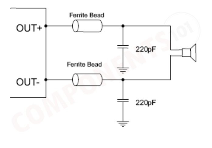
How to Reduce EMI (Electro Magnetic Interference)
A simple solution is to put an additional capacitor of 1000μF at the power supply terminal for power line coupling if the traces from the amplifier to speakers are short (< 20CM). Most applications require a ferrite bead filter as shown in Figure 1. The ferrite filter depresses EMI of around 1MHz and higher. When selecting a ferrite bead, choose one with high impedance at high frequencies and low impedance at low frequencies.
What are the Tips for Designing a PCB with PAM8406?
- Ground Planes: Employ extensive ground planes throughout the PCB. This minimises noise introduced by stray currents and creates a stable reference for your signal circuits.
- Trace Routing: Keep signal traces as short and direct as possible. This reduces their inductance and minimises signal attenuation.
- Decoupling Capacitors: Place decoupling capacitors strategically near the power pins of ICs to suppress unwanted noise on the power supply lines.
- Thermal Vias: Utilize thermal vias to transfer heat from hot components to lower copper layers that can act as heat spreaders.
- Component Placement: Position heat-generating components strategically to allow for airflow and minimise thermal coupling between them.
- Trace Width and Thickness: Ensure traces have sufficient width and thickness to handle the expected current without excessive voltage drops.
- Bypass Capacitors: Utilize bypass capacitors with appropriate capacitance values placed close to the power pins of ICs to filter out high-frequency noise on the power supply.
Applications of PAM8302
- Portable media players
- Navigation equipment's
- Portable Speakers
- 2-Way Radios
- Hands-Free Phones/Speaker Phones
- Cellular Phones
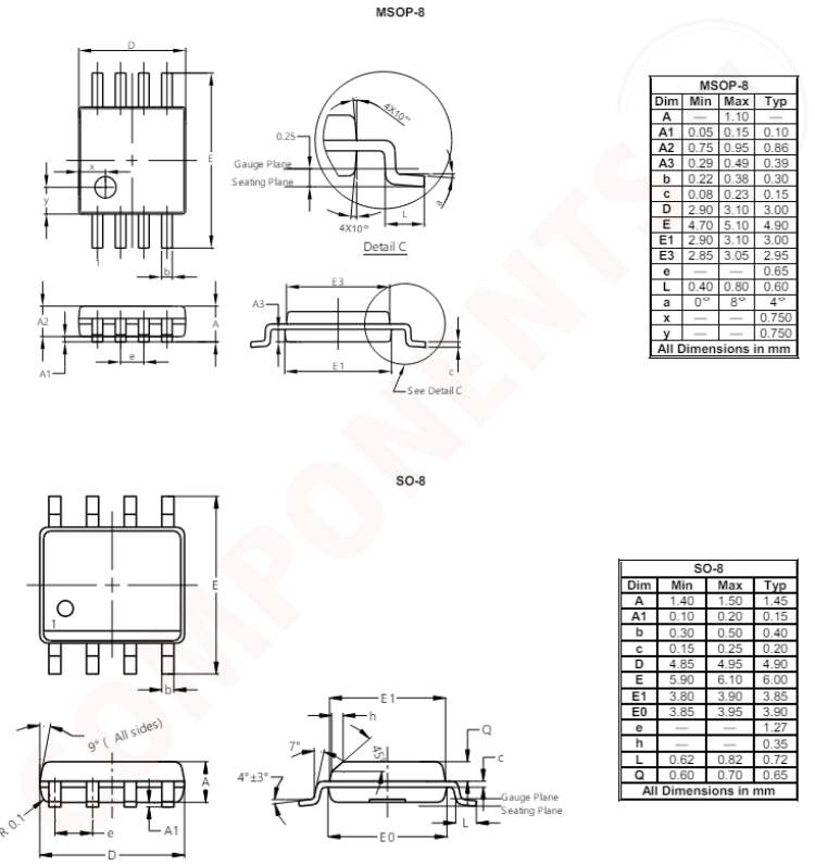
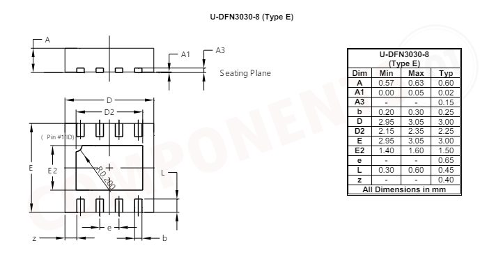
2D Model and Dimensions of PAM8302
Here you can find the mechanical drawings of PAM8302 along with its dimensions. The dimensions can be used to create custom footprints of the IC and be used for PCB or CAD modelling.