PAM8406 5W 2-Channel Class D Amplifier
The PAM8406 is a dual-channel 5W Class-D audio amplifier designed for driving stereo speakers. Due to its Class-D architecture, the PAM8406 provides high efficiency and low power consumption compared to traditional Class-AB amplifiers. This small IC can deliver up to 5W per channel with a 2Ω Load and 5V Power Supply. It can be operated in the voltage range from 2.5V to 6V, which makes this IC suitable for battery-powered devices. The PAM8406 offers low Total Harmonic Distortion (THD) for clear audio output and consumes low quiescent current, extending battery life in portable applications. The PAM8406 includes several protections features such as under-voltage lock-out, short-circuit protection, and overtemperature protection. UVLO disables outputs when the supply voltage drops to 2.0V, while SCP immediately disables outputs during a short circuit. Overtemperature protection activates at +150°C, with outputs re-enabled once the temperature drops by 30°C. Also, this IC comes with short circuit protection and thermal shutdown. The PAM8406 is available in the SOP-16L/SOP-16(EP) package.
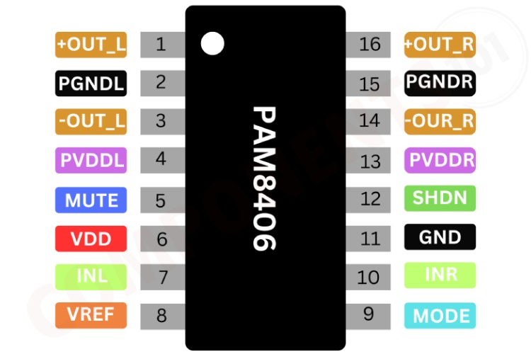
PAM8406 Pinout Configuration
Here are the pinout details for PAM8406.
| Pin Number | Pin Name | Function |
| 1 | +OUT_L | Left Channel Positive Output |
| 2 | PGNDL | Power GND |
| 3 | -OUT_L | Left Channel Negative Output |
| 4 | PVDDL | Power VDD |
| 5 | MUTE | Mute Control Input (active low) |
| 6 | VDD | Analog VDD |
| 7 | INL | Left Channel Input |
| 8 | VREF | Internal analog reference, connect a bypass capacitor from VREF to GND. |
| 9 | MODE | High: Class-D; Low: Class-AB |
| 10 | INR | Right Channel Input |
| 11 | GND | Analog GND |
| 12 | SHND | Shutdown Control Input (active low) |
| 13 | PVDDR | Power VDD |
| 14 | -OUT_R | Right Channel Negative Output |
| 15 | PGNDR | Power GND |
| 16 | +OUT_R | Right Channel Positive Output |
Features of PAM8406
PAM8406 Dual channel amplifier has the following key features:
- Alternative Output: Class-D or Class-AB
- 5W Output at 10% THD with a 2Ω Load and 5V Power Supply at Class-D Mode
- 3W Output at 10% THD with a 4Ω Load and 5V Power Supply
- Filter less, Low Quiescent Current and No EMI
- Low THD+N at Fully Output Range
- Superior Low Noise
- Efficiency up to 90% with Class-D Mode
- No Pop at Turn-On/Off
- Full Short-Circuit Protection with Auto Recovery
- Thermal Shutdown
- Few External Components to Save Space and Cost
Manufacturers of PAM8406:
The PAM8406 is originally manufactured by Diodes INC.
PAM8406 Equivalents
If you are looking for Equivalents of PAM8406 you can use PAM8403
PAM8406 Alternatives
If you are looking for an alternative for PAM8406 you can look at the other audio amplifier ICs from these. They may not have the same specifications, but they are some of the most popular audio amplifier ICS.
LM386, TDS7294, PAM8610, TDA1554, TDA2030, TDA7294, TDA7265, TDA7279, TDA2005, TDA2002, LM3886, LA4440
Note: Complete technical details can be found in the PAM8406 datasheet at this page’s end.
PAM8406 Schematics
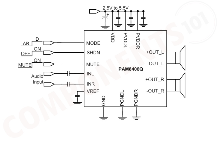
This circuit is a typical application of the PAM8406 dual-channel audio amplifier IC, designed for stereo audio amplification.
VDD, PVDDL and PVDDR pins are connected to the power supply, which can range from 2.5V to 5.5V. Capacitors are placed between these pins and ground to filter any noise and stabilise the voltage. GND, PGNDL and PGNDR pins are connected to the ground of the power supply. INL and INR are the audio inputs for the left and right channels. Input capacitors are used to block any DC component of the input signal.VREF pin is connected to a capacitor to the ground to stabilise the reference voltage for the inputs. MODE pin selects the operating mode of the amplifier. Connecting it to high (VDD) or low (ground) can change the mode between different gain settings or operating conditions.SHDN pin is used to shut down the amplifier to save power. Pulling it low will shut down the device while pulling it high will enable it. A MUTE pin is used to mute the audio output. Pulling it low will mute the output while pulling it high will enable it.
+OUT_L and -OUT_L are the differential outputs for the left channel, connected to the left speaker.+OUT_R and -OUT_R are the differential outputs for the right channel, connected to the right speaker.
Troubleshooting Tips for PAM8406
My amplifier circuit is not working (not getting any sound output):
This could be due to various factors like loose connections, a muted amplifier, or a faulty source device. To find the fault first Check all cable connections between the amplifier, source device (player, phone etc.), and speakers. Ensure they're securely plugged in. Verify the values of resistors. Try it with a different source device to isolate the problem. Check the mute and shutdown pin status, if it is not high pull, it to high.
Getting only Distorted Sound:
Distortion can arise from blown speakers, faulty amplifier components, or clipping (an amplifier trying to output more power than it can). To solve this Lower the volume. Clipping often happens at high volumes. Also, check the speakers for any tears or damage in the cones. Damaged speakers can cause distortion.
My amplifier output is very Low:
Low output could be caused by incorrect speaker impedance matching, low power input source or internal amplifier issues. Verify the speaker impedance matches the amplifier's specifications.
When I am using the PAM8406 board with Bluetooth module, there is a static noise coming out. How to fix it?
The static noise can be a result of shared ground. For use an isolated dc supply to power the Bluetooth module.
Design tips for PAM8406
When designing with the PAM8406, it's crucial to ensure proper power supply decoupling to minimize output THD and PSRR. Optimal decoupling is achieved with two capacitors targeting different types of noise. For high-frequency transients, a 1.0μF low-ESR ceramic capacitor should be placed close to the VDD terminal. A larger capacitor, typically 20μF or greater, should be placed near the audio power amplifier to filter low-frequency noise. Input capacitors should be carefully chosen to balance system cost, size, and performance, forming a high-pass filter with the input resistance. Smaller capacitors can help minimize turn-on pops by reducing the charge needed to reach quiescent DC voltage. The Analog Reference Bypass Capacitor is critical for reducing noise and ensuring smooth startup. A 0.47μF to 1.0μF ceramic capacitor is recommended for optimal THD and noise performance.
For PCB design, extensive ground planes, short signal traces, strategically placed decoupling and bypass capacitors, thermal vias, and appropriate trace widths are essential for minimizing noise and ensuring stable operation. Additional tips include connecting the speaker before powering on when using LC filters, adding ferrite beads to suppress EMI without LC filters, and avoiding excessively large input signals to prevent output clipping and potential device damage.
Applications of PAM8406
- Car Radio Systems
- Portable Audio Systems
- Battery-Powered amplifiers
- Home Audio Systems
- Stereo Systems
- Home Theaters
- Public Address Systems
- DIY Audio Projects
- Television Audio Amplifiers
- Computer Audio Systems
- Small Signal Amplifiers
- Interactive Devices
- Alarm and Notification Systems
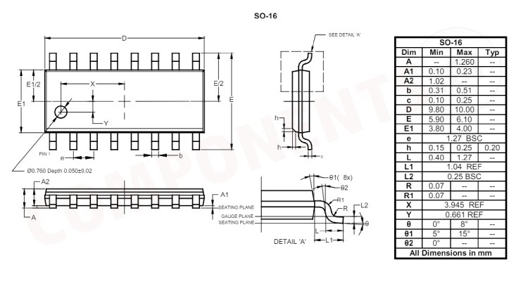
2D Model and Dimensions of PAM8406
Here you can find the mechanical drawings of PAM8406 along with its dimensions. The dimensions can be used to create custom footprints of the IC and be used for PCB or CAD modelling.