BQ24074 Single-Cell Linear Battery Charger with Power Path
The BQ24074 is a Li-Ion/li-poly linear charger with built-in power path management, which allows the device to power the system while charging the battery. This is particularly useful in applications where the battery must be charged, and the system needs to be powered simultaneously. The BQ24074 supports charging current up to 1.5 A. This chip can handle a higher input voltage of up to 28V and input overvoltage protection which is very useful in unregulated adapters. Additionally, the input dynamic power management prevents the IC from crashing incorrectly configured USB sources. The battery can be charged in three phases using this IC: conditioning, constant current, and constant voltage. In all cases, the BQ24074 monitors the IC temperature and reduces the charge current if the temperature threshold is exceeded. The input current limit and charge current can be programmed by using external resistors. The BQ24074 is available VQFN package, which is ideal for portable and small products.
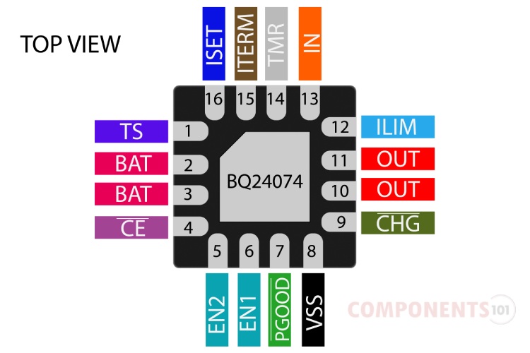
BQ24074 Pinout Configuration
Here are the pinout details for BQ24074.
| PIN NO | PIN NAME | DESCRIPTION |
| 1 | TS | External NTC Thermistor Input |
| 2,3 | BAT | Charger Power Stage Output and Battery Voltage Sense Input. |
| 4 | CE | Charge Enable Active-Low Input. |
| 5 | EN2 | Input Current Limit Configuration Inputs. |
| 6 | EN1 | Input Current Limit Configuration Inputs. |
| 7 | PGOOD | Open-drain Power Good Status Indication Output. |
| 8 | VSS | Ground |
| 9 | CHG | Open-Drain Charging Status Indication Output. |
| 10,11 | OUT | System Supply Output |
| 12 | ILIM | Adjustable Current Limit Programming Input |
| 13 | IN | Input Power Connection |
| 14 | TMR | Timer Programming Input |
| 15 | TD | Termination Disable Input |
| 16 | ISET | Fast Charge Current Programming Input |
Features of BQ24074
BQ24074 single-cell lithium-ion battery charger has the following key features:
- 28V Input rating with overvoltage protection.
- Integrated dynamic power path management (DPPM) function simultaneously and independently powers the system and charges the battery.
- Supports up to 1.5-A charge current with current monitoring output (ISET).
- Programmable input current limit up to 1.5 A.
- Programmable termination current
- Programmable pre-charge and fast-charge safety timers
- Reverse current, short-circuit and thermal protection.
- NTC thermistor input
- Proprietary start-up sequence limits inrush current
- Status indication – charging/done, power good.
Manufacturers of BQ24074:
The BQ24074 is manufactured by Texas Instruments. There are no alternative manufacturers for the same part number as of the date of writing this article. The part number BQ24074 available is BQ24074RGTR, you can use this to order this chip directly from the suppliers.
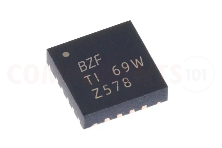
How to Identify BQ24074
The BQ24074 will have marking BZF or NXK. You can use this marking to identify the BQ24074.
BQ24074 Equivalents
If you are looking for an equivalent or replacement for BQ24074 you can use these ICs BQ24072, BQ24073, BQ24075, BQ2406, BQ24078, BQ24079 from the same family.
| PART NUMBER | Input OVP threshold | Battery Voltage Threshold (VBAT) | VOUT | Output voltage threshold (VDPPM) |
| BQ24072 | 6.6 V | 4.2 V | VBAT + 225 mV | VOut(REG) – 100 mV |
| BQ24073 | 6.6 V | 4.2 V | 4.4 V | VOut(REG) – 100 mV |
| BQ24074 | 10.5 V | 4.2 V | 4.4 V | VOut(REG) – 100 mV |
| BQ24075 | 6.6 V | 4.2 V | 5.5 V | 4.3 V |
| BQ24076 | 6.6 V | 4.4 V | VBAT + 225 mV | VOut(REG) – 100 mV |
| BQ24078 | 6.6 V | 4.35 V | VBAT + 225 mV | VOut(REG) – 100 mV |
| BQ24079 | 6.6 V | 4.1 V | 5.5 V | 4.3 V |
| BQ24072T | 6.6 V | 4.2 V | VBAT + 225 mV | VOut(REG) – 100 mV |
| BQ24075T | 6.6 V | 4.2 V | 5.5 V | 4.3 V |
| BQ24079T | 6.6 V | 4.1 V | 5.5 V | 4.3 V |
You could also check the BQ25185, which Same functionality with a different pin-out.
BQ24074 Alternatives
If you are looking for an alternative for BQ24074 you can look at the other IC from these.
BQ29700, MCP73831, TP5000, TP5100 module, TP4056, MAX1898, LTC4054, MAX1555
Note: Complete technical details can be found in the BQ24074 datasheet at this page’s end.
BQ24074 Circuit Diagram
The following image shows the typical circuit diagram for BQ24074.
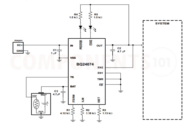
In the circuit, we can see that the BQ24074 takes the input supply through the IN pin, and a smoothing capacitor is also connected very close to this pin. The thermistor is connected between the TS pin and the ground. The adjustable current limit, fast charge current limit and termination current are set using various resistors connected to the respective pins. We can monitor the charging status and processor status using the connected LEDs. The capacitors used here are for stabilizing the circuit.
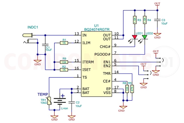
Here in this practical charger circuit built around the BQ24074, we have set the charge current to 1A using the resistor R2. The chip enables and timer pins were pulled down to the ground and jumpers were provided for EN1 and EN2 pins. Using these jumpers we can configure the input current limit. A red LED is provided to show the charging status and a green LED is provided to show the power good status. The thermistor must be placed close to the battery to get the appropriate temperature readings and thermal protection.
BQ24074 Circuit is not Working?
- The battery is not charging: Check the connections properly, and check whether the grounds of the input supply and battery are properly connected to the ground pin of the IC. Also, make sure that the battery is not flat-out dead.
- The charging current is too low: Check the temperature of the IC, that is if the generated heat does not dissipate the charging current will be limited by the IC. Also, make sure you have set the charging current and input current limits using the appropriate resistor values connected to the Iset and ILim pins.
- The circuit’s performance is not stable: Ensure that the input (USB/Adapter) is stable and within the specified voltage range. Also, check whether the supply provides enough current to charge the battery. Use a high-frequency decoupling capacitor (ceramic) on the power pin, input, output and battery pins.
Things to Consider When using BQ24074:
Does the IC have reverse voltage protection?
The BQ24074 does not have reverse-voltage protection on its input. Applying a reverse voltage to the input of the BQ24074 can damage the IC.
Is it possible to charge more than one battery with BQ24074?
No, the BQ24074 is designed to charge single-cell lithium-ion/polymer batteries.
What is the maximum input voltage BQ24074 can handle?
The absolute maximum voltage BQ24074 can handle is 28V. The recommended maximum input voltage is 10.2V and the over-voltage protection will be triggered at 10.5V.
Are there any ready-made modules available for BQ24074?
You can find various BQ24074 solar chargers and battery charging modules for single-cell batteries. The ability to handle higher absolute maximum voltage makes the BQ24074 a perfect choice for such small solar applications.
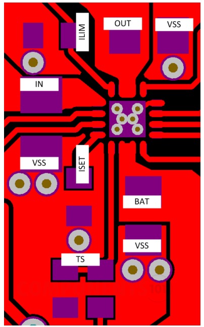
What are the design considerations when designing a PCB using BQ24074?
The BQ24074 is packaged in a thermally enhanced MLP package. The package includes a thermal pad to provide effective thermal contact between the IC and the printed circuit board (PCB). The power pad should be directly connected to the VSS pin.
- To obtain optimal performance, the decoupling capacitor from IN to GND (thermal pad) and the output filter capacitors from OUT to GND (thermal pad) should be placed as close as possible to the BQ24074, with short trace runs to both IN, OUT and GND (thermal pad).
- All low-current GND connections should be kept separate from the high-current charge or discharge paths from the battery. Use a single-point ground technique incorporating both the small signal ground path and the power ground path.
- The high current charge paths into the IN pin and from the OUT pin must be sized appropriately for the maximum charge current in order to avoid voltage drops in these traces.
- The BQ24074 family is packaged in a thermally enhanced MLP package. The package includes a thermal pad to provide effective thermal contact between the IC and the printed circuit board (PCB); this thermal pad is also the main ground connection for the device. Connect the thermal pad to the PCB ground connection. Full PCB design guidelines for this package are provided in the QFN/SON PCB Attachment Application Note.
Applications of BQ24074
- TWS Charging case and headphones.
- Gaming accessory
- Video doorbells, IP network cameras
- Asset tracking and fleet management
- Portable medical devices
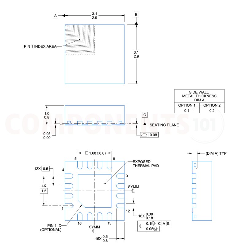
2D Model and Dimensions of BQ24074
Here you can find the mechanical drawings of BQ24074 along with its dimensions. The dimensions can be used to create custom footprints of the module and be used for PCB or CAD modelling.