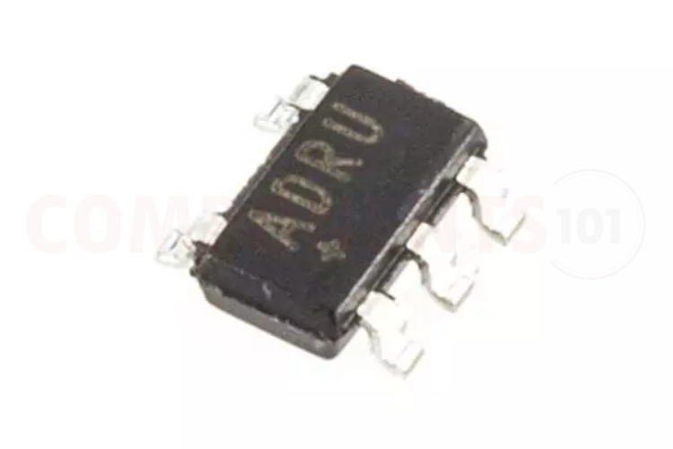
MAX1555- Dual Input Single-Cell Lithium-ion Battery Charger
The MAX1555 is an efficient battery charger IC designed for single-cell lithium-ion and lithium-polymer batteries. The MAX1555 supports a wide input voltage range which makes the IC suitable to charge from USB and AC power adapters. It includes several battery protection features such as thermal regulation and overcharging of the battery. When the IC exceeds the temperature limit it will decrease the charging current automatically. The MAX1555 can provide a charging current of up to 280mA, which is suitable for small-sized batteries The MAX1555 comes in a small package, making it ideal for use in compact electronic devices where space is limited. It's commonly used in portable electronic devices like smartphones, tablets, and digital cameras to charge the battery safely and efficiently.
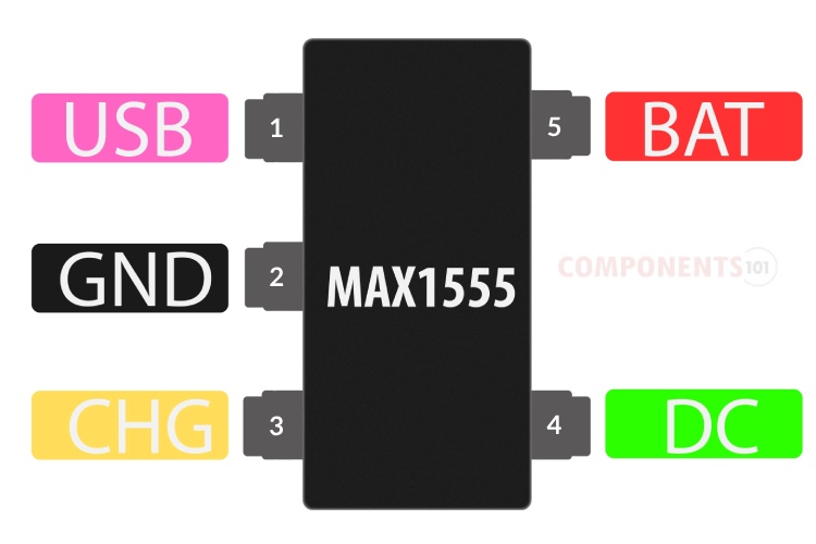
MAX1555 Pinout Configuration
Here are the pinout details for MAX1555.
| PIN NO | PIN NAME | DESCRIPTION |
| 1 | USB | USB Port Charger Supply Input |
| 2 | GND | Ground |
| 3 | CHG | Active-Low Open-Drain Charge Status Indicator |
| 4 | DC | DC Charger Supply Input for an AC Adapter. |
| 5 | BAT | Battery Connection |
Manufacturers of MAX1555:
The MAX1555 is manufactured by Analog devices. There are no alternative manufacturers for the same part number as of the date of writing this article.
MAX1555 Equivalents
If you are looking for an equivalent or replacement for MAX1555 you can use the MAX1551 from the same family.
MAX1555 Alternatives
If you are looking for an alternative for MAX1555 you can look at the other IC from these.
BQ29700, MCP7383, TP5000, TP5100 module, TP4056, MAX1898, LTC4054, BQ24074
Note: Complete technical details can be found in the MAX1555 datasheet at this page’s end.
Features of MAX1555
MAX1555 CMOS Dual input single-cell lithium-ion battery charger has the following key features:
- Charge from a USB or AC Adapter.
- Automatic Switchover when AC Adapter is Plugged In.
- On-Chip Thermal Limiting Simplifies Board Design.
- Charge Status Indicator.
- 5-Pin Thin SOT23 Package.
- Input voltage up to 7V.
- The typical charge current is up to 280mA.
MAX1555 Circuit Diagram
The following image shows the typical circuit diagram for MAX1555.
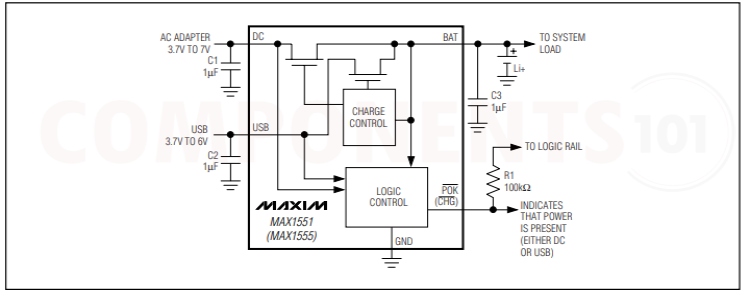
We can design a lot of battery charging from this circuit. In this circuit, we can connect either ac adapter or USB as input power as the source, note that we can't use both of them at a time. The battery is connected to the battery pin of the IC. In this circuit ceramic bypass capacitors are connected to DC, USB, and BAT pins to stabilize the circuit. Both the grounds of the battery and the input adapter are connected to the ground pin of the IC.
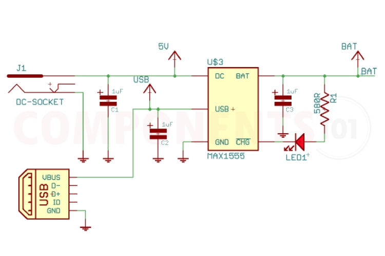
And here is a practical circuit built around the MAX1555. As mentioned earlier the MAX1555 can take two input sources. So we have provided both DC input jack and micro-USB input to the circuit. From the DC input, the IC will be able to charge the battery with a maximum current of 280mA, while with the USB input, it is limited to 100mA.
MAX1555 Circuit is not Working?
- The battery is not charging: Check the connections properly, and check whether the grounds of the input supply and battery are properly connected to the ground pin of the IC. Also, make sure that the battery is not flat-out dead.
- The charging current is too low: Check the temperature of the IC, that is if the generated heat does not dissipate the charging current will be limited by the IC. Also, with USB input pin the charging current is limited to 100mA. for the maximum charging current use, the DC input.
- The circuit’s performance is not stable: Ensure that the input (USB/Adapter) is stable and within the specified voltage range. Also, check whether the supply provides enough current to charge the battery. Use a good bypass capacitor to prevent power disturbance.
Things to Consider When Using MAX1555 Charger IC
Is it possible to charge a battery with a USB and DC adapter at the same time?
The MAX1555 can charge from either the USB input or the DC input. The battery does not charge from both sources at the same time. The MAX1555 automatically detects the active input and charge from that. If both power sources are active, the DC input takes precedence.
Is it possible to charge more than one battery with MAX1555?
No, the MAX1555 is designed to charge single-cell lithium-ion/polymer batteries.
Does the working of the circuit depend on the temperature?
Yes. An internal thermal control loop simplifies PCB board layout and allows optimum charging rate without the thermal limits imposed by worst-case battery and input voltage. When the MAX1555 thermal limits are reached, the chargers do not shut down but simply reduce the charging current by 17mA/°C above a die temperature of +110°C.
What are the design considerations when designing a PCB using CD4067?
The device reduces the power dissipation at BAT to prevent overheating. This allows the board design to be optimized for compact size and typical thermal conditions. When the MAX1551/ MAX1555 thermal limits are reached, the chargers do not shut down but progressively reduce the charging current by 17mA/°C above a die temperature of +110°C. Solder the MAX1555s’ GND to a large ground plane to help dissipate power and keep the die temperature below the thermal limit. The USB charge current of 100mA is unlikely to induce thermal limiting. Use ceramic bypass capacitors at DC, USB, and BAT pins. Mount these capacitors within 1cm of their respective pins. X7R and X5R dielectrics are recommended.
Is there any different package or part number variations of MAX1555?
No. The MAX1555 is only available in one package (SOT-23-5) and only with one part number: MAX1555EZK-T.
Applications of MAX1555
- PDAs
- Wireless Appliances
- Cell Phones
- Digital Cameras
- Battery Management System
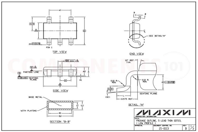
2D Model and Dimensions of MAX1555
Here you can find the mechanical drawings of MAX1555 along with its dimensions. The dimensions can be used to create custom footprints of the module and be used for PCB or CAD modelling.
