MCP73831T Single-Cell Li-Ion, Li-Polymer Charge Management Controllers
The MCP73831 devices are extremely sophisticated linear charge management controllers for use in situations with limited space and a tight budget. The MCP73831 devices are offered in a 5-Lead SOT-23 configuration. In addition to its tiny physical size, the MCP73831 is well suited for portable applications because of the low requirement for external components. The MCP73831 complies with all the requirements governing the USB power bus for applications charging from a USB port. The charge algorithm used by the MCP73831 is constant-current/constant voltage with configurable preconditioning and charge termination. To meet evolving battery charging needs, the constant voltage regulation is fixed with four options: 4.20V, 4.35V, 4.40V, or 4.50V. One external resistor is used to set the constant current value. The MCP73831 limits the charge current based on die temperature during high power or high ambient conditions. This thermal regulation optimizes the charge cycle time while maintaining device reliability.
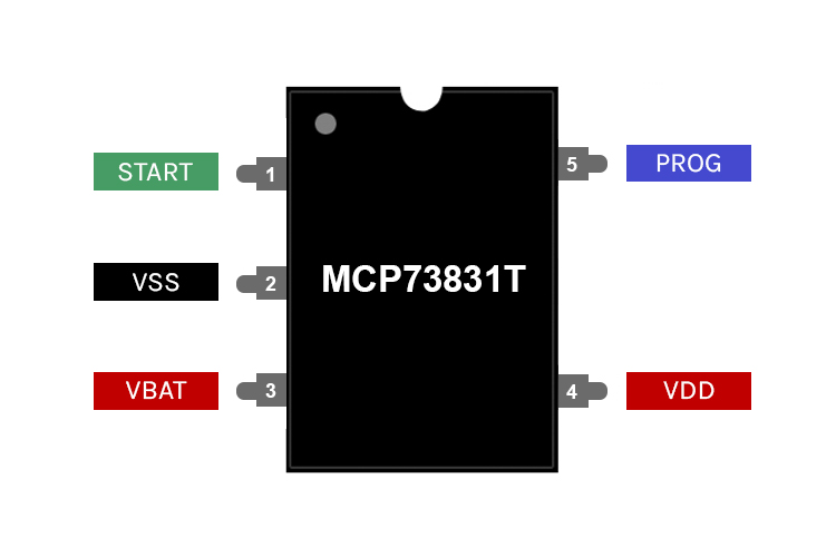
MCP73831 Pinout Configuration
|
Pin Number |
Pin Name |
Description |
|
1 |
STAT |
Charge Status Output |
|
2 |
VSS |
Battery Management 0V Reference |
|
3 |
VBAT |
Battery Charge Control Output |
|
4 |
VDD |
Battery Management Input Supply |
|
5 |
PROG |
Current Regulation Set and Charge Control Enable |
MCP73831T Features
- Linear Charge Management Controller:
- Integrated Pass Transistor
- Integrated Current Sense
- Reverse Discharge Protection
- High Accuracy Pre-set Voltage Regulation
- Four Voltage Regulation Options:
- 4.20V, 4.35V, 4.40V, 4.50V
- Programmable Charge Current: 15 mA to 500 mA
- Selectable Preconditioning:
- 10%, 20%, 40%, or Disable
- Selectable End-of-Charge Control:
- 5%, 7.5%, 10%, or 20%
- Charge Status Output- Tri-State Output
- Automatic Power-Down
- Thermal Regulation
- Temperature Range: -40°C to +85°C
- Packaging: 5-Lead, SOT-23
Absolute Maximum Ratings
- VDD: 7.0V
- All Inputs and Outputs w.r.t. VSS: -0.3 to (VDD+0.3)V
- Maximum Junction Temperature, TJ: Internally Limited
- Storage temperature: -65°C to +150°C
- ESD protection on all pins:
- Human Body Model (1.5kΩ in Series with 100pF): ≥ 4kV
- Machine Model (200pF, No Series Resistance): 400V
Other Single Cell Chargers
Note: Complete technical details can be found in the MCP73831 datasheet at this page’s end.
How To Use MCP73831?
The schematics below show the typical application diagram of an MCP73831. As mentioned earlier, it only requires a very minimal number of components that include the current programming resistor, status led, and filter capacitors.
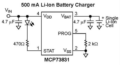
Charge current can be set by placing a programming resistor in between the PROG VSS pins. The program resistor and the charge current are calculated using the following equation:
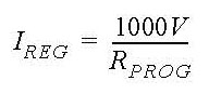
where RPROG = kOhms and IREG = mA
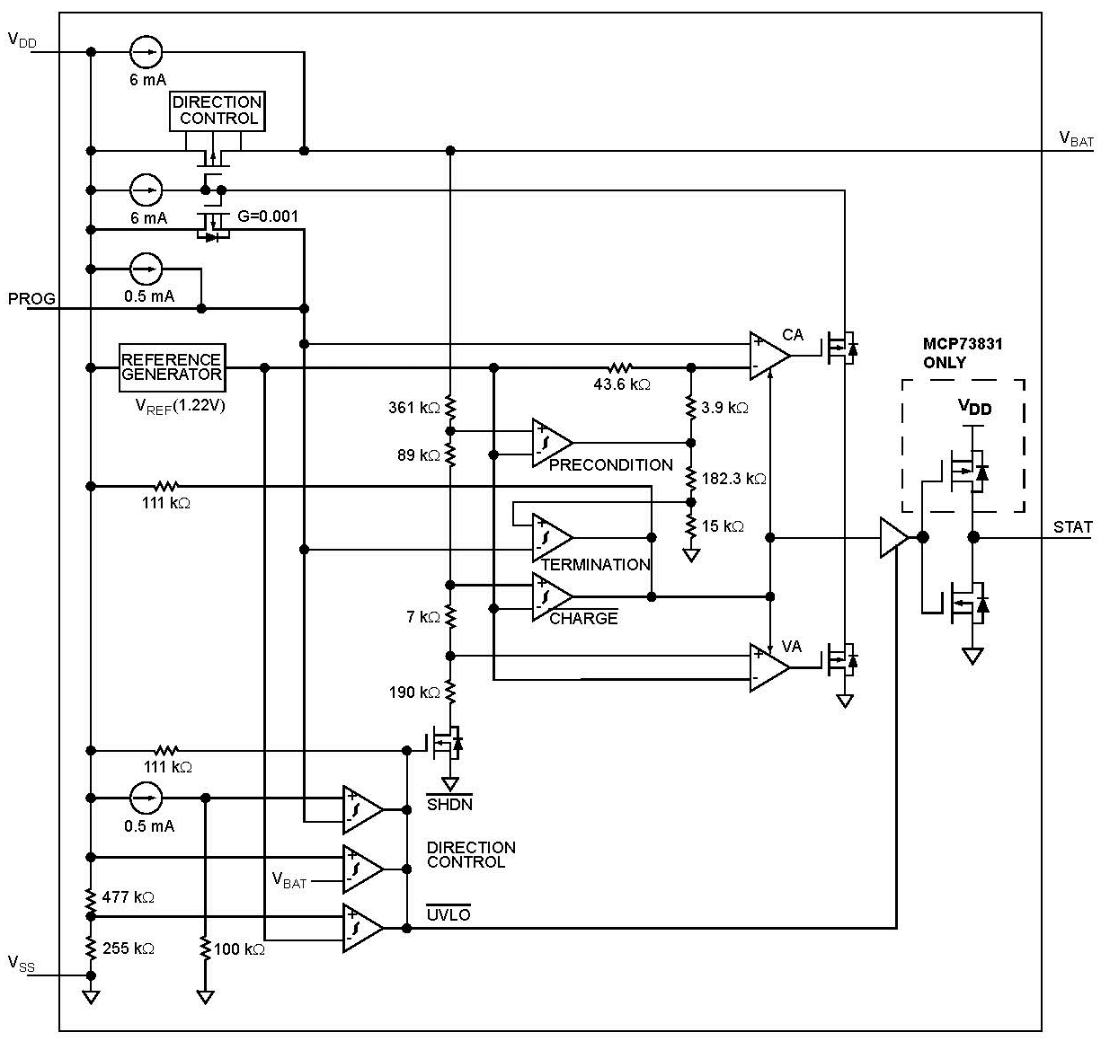
Functional Block Diagram
Applications
- Lithium-Ion/Lithium-Polymer Battery Chargers
- Personal Data Assistants
- Cellular Telephones
- Digital Cameras
- MP3 Players
- Bluetooth Headsets
- USB Chargers
DC Characteristics
|
Parameters |
Sym |
Min |
Тур |
Max |
Units |
Conditions |
|
Supply Input |
||||||
|
Supply Voltage |
VDD |
3.75 |
|
6 |
V |
|
|
Supply Current |
Iss |
|
510 |
1500 |
μA |
Charging |
|
|
53 |
200 |
μA |
Charge Complete, No Battery |
||
|
|
25 |
50 |
μA |
PROG Floating |
||
|
|
1 |
5 |
μA |
VDD ≤ (VBAT-50 mV) |
||
|
- |
0.1 |
2 |
μA |
VDD < VSTOP |
||
|
UVLO Start Threshold |
VSTART |
3.3 |
3.45 |
3.6 |
|
VDD Low-to-High |
|
UVLO Stop Threshold |
VSTOP |
3.2 |
3.38 |
3.5 |
V |
VDD High-to-Low |
|
UVLO Hysteresis |
VHYS |
|
70 |
|
mV |
|
|
Voltage Regulation (Constant-Voltage Mode) |
||||||
|
Regulated Output Voltage |
VREG |
4.168 |
4.2 |
4.232 |
V |
MCP7383X-2 |
|
4.317 |
4.35 |
4.383 |
V |
MCP7383X-3 |
||
|
4.367 |
4.4 |
4.433 |
V |
MCP7383X-4 |
||
|
4.466 |
4.5 |
4.534 |
V |
MCP7383X-5 |
||
|
|
|
|
|
VDD = [VREG(typical) +1V] OUT = 10 MA TA = -5°C to +55°C |
||
|
Line Regulation |
(▲VBAT/ VBAT/▲VDD) |
|
0.09 |
0.3 |
%/V |
VDD = [VREG(typical) +1V] to 6V, lOUT = 10 mA |
|
Load Regulation |
▲VBAT/VBATI |
|
0.05 |
0.3 |
% |
OUT = 10 mA to 50 mA VDD = [VREG(typical) +1V] |
|
Supply Ripple Attenuation |
PSRR |
|
52 |
|
dB |
lOUT 10 mA, 10Hz to 1 kHz |
|
|
47 |
|
dB |
OUT 10 mA, 10Hz to 10 kHz |
||
|
|
22 |
|
dB |
OUT 10 mA, 10Hz to 1 MHz |
||
|
Current Regulation (Fast Charge Constant-Current Mode) |
||||||
|
Fast Charge Current Regulation |
IREG |
90 |
100 |
110 |
mA |
PROG 10 KS2 |
|
450 |
505 |
550 |
mA |
PROG= 2.0 KQ, Note 1 |
||
|
12.5 |
14.5 |
16.5 |
mA |
PROG= 67 KQ |
||
|
|
|
|
|
TA = -5°C to +55°C |
||
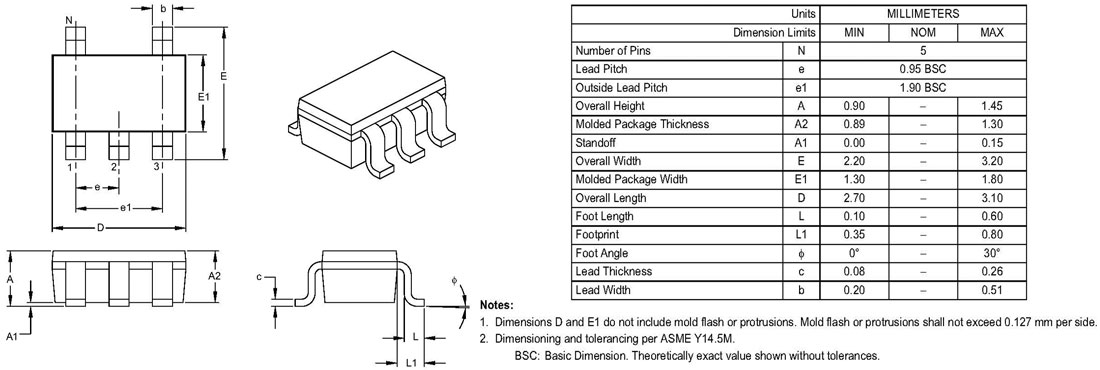
2D-Model and Dimensions