BQ29700 - Single Cell Battery Protection IC
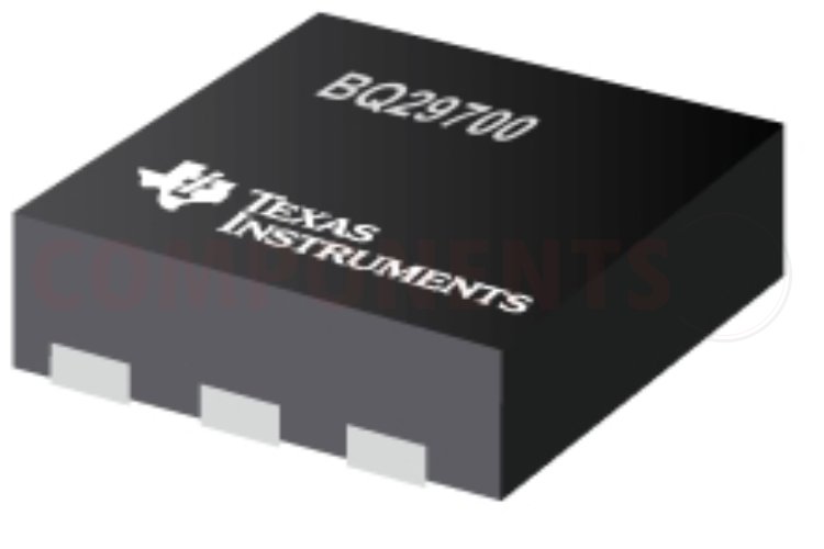
This BQ29700 is a single-cell Li-ion/Li-polymer battery protection IC from Texas Instruments. BQ29700 features all the standard protection features such as Overcharge, Over-discharge, Charge overcurrent, Discharge overcurrent, and Load short-circuit protections. The BQ29700 uses a few external components for its work. It can monitor high charge and discharge current with the help of external FETs. It is also very useful to monitor depleted or overcharged batteries. The Zero voltage charging enables the BQ29700 to charge a depleted battery. The BQ29700 is available in a tiny DSE package, which measures 1.5x1.5x0.75mm in dimensions.
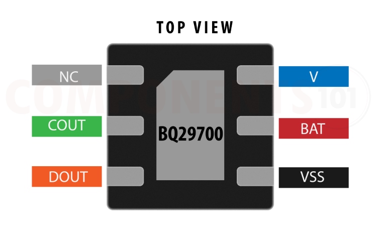
BQ29700 Pinout Configuration
Here are the pinout details for the BQ29700.
| PIN NO | PIN NAME | DESCRIPTION |
| 1 | NC | No Connection (electrically open, do not connect to BAT or VSS) |
| 2 | COUT | Gate Drive Output for Charge FET |
| 3 | DOUT | Gate Drive Output for Discharge FET |
| 4 | VSS | Ground pin |
| 5 | BAT | VDD pin |
| 6 | V– | Input pin for charger negative voltage |
Manufacturers of BQ29700:
BQ29700 is manufactured only by Texas Instruments
BQ29700 Equivalents
If you are looking for a pin-to-pin replacement for BQ29700 you can use the BQ29701, BQ29702, BQ29703, BQ29704 and BQ29705 from the same family. Here is the list of all the devices available in the same family. the differences between them are also included in the table below.
| PART NUMBER |
OVP (V) | OVP DELAY (s) |
UVP (V) | UVP DELAY (ms) |
OCC (V) | OCC DELAY (ms) |
OCD (V) | OCD DELAY (ms) |
SCD (V) | SCD DELAY (µs) |
| BQ29700 | 4.275 | 1.25 | 2.8 | 144 | –0.100 | 8 | 0.1 | 20 | 0.5 | 250 |
| BQ29701 | 4.28 | 1.25 | 2.3 | 144 | –0.100 | 8 | 0.125 | 8 | 0.5 | 250 |
| BQ29702 | 4.35 | 1 | 2.8 | 96 | –0.155 | 8 | 0.16 | 16 | 0.3 | 250 |
| BQ29703 | 4.425 |
1.25 |
2.3 |
20 |
–0.100 | 8 | 0.16 | 8 | 0.5 | 250 |
| BQ29704 | 4.425 | 1.25 | 2.5 | 20 | –0.100 | 8 | 0.125 | 8 | 0.5 | 250 |
| BQ29705 | 4.425 | 1.25 | 2.5 | 20 | –0.100 | 8 | 0.15 | 8 | 0.5 | 250 |
| BQ29706 | 3.85 | 1.25 | 2.5 | 144 | –0.150 | 8 | 0.2 | 8 | 0.6 | 250 |
| BQ29707 | 4.28 | 1 | 2.8 | 96 | –0.090 | 6 | 0.09 | 16 | 0.3 | 250 |
| BQ29716 | 4.425 | 1.25 | 2.3 | 20 | –0.100 | 8 | 0.165 | 8 | 0.5 | 250 |
| BQ29717 | 4.425 | 1.25 | 2.5 | 20 | –0.100 | 8 | 0.13 | 8 | 0.5 | 250 |
| BQ29718 | 4.425 | 1.25 | 2.5 | 20 | –0.100 | 8 | 0.1 | 8 | 0.5 | 250 |
| BQ29723 | 4.425 | 1 | 2.5 | 96 | –0.060 | 4 | 0.1 | 8 | 0.3 | 250 |
| BQ29728 | 4.28 | 1.25 | 2.8 | 144 | –0.100 | 8 | 0.15 | 8 | 0.5 | 250 |
| BQ29729 | 4.275 | 1.25 | 2.3 | 20 | –0.100 | 8 | 0.13 | 8 | 0.5 | 250 |
| BQ29732 | 4.28 | 1.25 | 2.5 | 144 | –0.100 | 8 | 0.19 | 8 | 0.5 | 250 |
| BQ29733 | 4.4 | 1.25 | 2.8 | 20 | –0.100 | 8 | 0.12 | 8 | 0.3 | 250 |
| BQ29737 | 4.25 | 1 | 2.8 | 96 | –0.050 | 16 | 0.1 | 16 | 0.3 | 250 |
| BQ297xy | 3.85–4.6 | 0.25, 1, 1.25, 4.5 |
2.0–2.8 | 20, 96, 125, 144 |
–0.045 to –0.155 |
4, 6, 8, 16 | 0.090–0.20 0 |
8, 16, 20, 48 |
0.3, 0.4, 0.5, 0.6 |
250 |
* OVP - Overcharge detection, UVP- Over-discharge detection, OCC - Charge overcurrent detection, OCD - Discharge overcurrent detection, SCD - Load short-circuit detection
BQ29700 Alternatives
If you are looking for an alternative for BQ29700 you can look at the other IC from these.
DW01, AP9101CAK6-ANTRG1, FS312F
Note: Complete technical details can be found in the BQ29700 datasheet at this page’s end.
Features of BQ29700
BQ29700 has the following key features:
- Wide Input voltage range - 0.3 V to 12 V
- FET drive: FET drive for high current Measurement
- Over-voltage protection at 4.25V
- Under-voltage protection at 2.8V
- Short circuit detection delay of 250μS
- Overcurrent protection Voltage sensing across external FETs
- Fault detection – Overcharge detection, Over-discharge detection,– Charge overcurrent detection, Discharge overcurrent detection, Load short-circuit detection.
- Zero voltage charging for depleted battery
- Factory-programmed fault protection
- Modes of operation without battery charger enabled
- Wide Operating temperature range –40°C to +85°C
- Small Package: – 6-pin DSE
BQ29700 Schematics
The following image shows the typical BQ29700 circuit diagram.
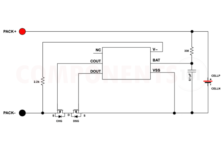
In the circuit, we can see that the number of external components is very minimal. The V-pin is connected to the negative rails via a 2.2k resistor. The Bat pin is connected to the positive rail via a 330 ohms resistor. A capacitor of value 100nf is also connected to the Bat pin, these resistors and capacitor form an RC filter circuit to provide better stability. the charge and discharge MOSFETs are controlled using the Cout and Dout pins. The circuit is very similar to the popular battery protection circuit built around the DW01 chip.
Troubleshooting Tips for BQ29700
BQ29700 Not Responding to Fault Conditions
Double-check all connections between the BQ29700 and external components, such as the battery, FETs, and sensing circuitry. Poor connections or incorrect wiring can cause malfunctions. A faulty MOSFET can also cause similar issues. SO check the MOSFETs too.
There is no voltage at the output after connecting the battery to the BQ29700 circuit.
Connect the charger to activate the protection circuit. The protection circuit needed to be activated with a charger after reconnection.
The battery is not charging.
Make sure the MOSFET is in good condition. A fault BQ29700 can also cause the same issue.
Design tips for BQ29700
- Ensure the external power FETs are adequately compensated for heat dissipation with sufficient thermal heat spreader based on worst-case power delivery.
- The connection between the two external power FETs should be very close to ensure there is not an additional drop for fault sensing.
- The input RC filter on the BAT pin should be close to the terminal of the IC.
- Select the proper device from the BQ29700 family depending on your requirements. Each chip will have different threshold levels. Refer to the table given above.
Applications of BQ29700
- Tablet PCs
- Mobile handsets
- Handheld data terminals
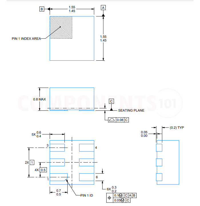
2D model and dimensions of BQ29700
Here you can find the mechanical drawings of BQ29700 along with its dimensions. The dimensions can be used to create custom footprints of the module and be used for PCB or CAD modelling.