MAX1898 Linear Charger for Single-Cell Li+ Battery
The MAX1898 is a highly advanced and efficient charging solution for 1-cell lithium-ion (Li+) batteries, when coupled with an external PNP or PMOS transistor. It delivers precise constant-current/constant-voltage charging with exceptional battery regulation voltage accuracy of ±0.75%, promoting optimal battery performance and cycle life. Moreover, the MAX1898 eliminates the need for external current-sense resistors, thanks to its internal current-sensing capability. To facilitate ease of use and provide crucial monitoring information, the MAX1898 includes outputs that enable charge status monitoring, detection of input power source presence, and measurement of charge current. The device also features several additional functions, including shutdown, selectable charge termination safety timer, optional charge-cycle restart without input-power cycling, and low-current preconditioning for deeply discharged cells.
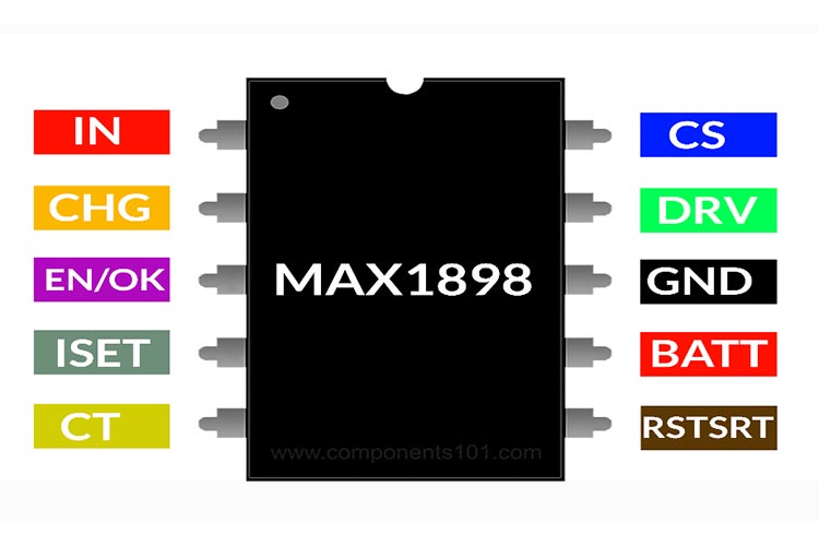
MAX1898 Pinout Configuration
|
Pin Number |
Pin Name |
Description |
|
1 |
IN |
Sense Input. Detects power source; positive side of internal current-sense resistor. |
|
2 |
CHG |
Open-Drain LED Driver. See Table 1 for CHG output states. |
|
3 |
EN/OK |
Logic-Level Enable Input and Input Power OK Output. Hold low to disable charger. Float for normal operation, drive with an open-drain device to utilize both pin functions, or connect through 10kOhms for logic controlled ON/OFF |
|
4 |
ISET |
ISET serves two functions. It provides an analog output proportional to the actual charge current. Output current from ISET is 1mA per amp of battery charging current. The charging current is set by connecting a resistor from ISET to ground. |
|
5 |
CT |
Safety Charge Timer Control. Connect timer capacitor to program safety time-out interval; 100nF for approximately three hours. Connect to GND to disable the timer function. |
|
6 |
RSTSRT |
Automatic-Restart Control Pin. When tied to GND, a new charging cycle starts if the cell drops 200mV below the battery regulation threshold. The restart threshold may be lowered by connecting a resistor from RSTRT to ground. |
|
7 |
BATT |
Battery Sense Input. Positive terminal of single Li+ cell. |
|
8 |
GND |
Ground |
|
9 |
DRV |
External Transistor Driver. This pin drives the gate/base of an external PMOS/PNP pass transistor. |
|
10 |
CS |
Current-Sense Input. Negative side of internal current-sense resistor. Connect to source/emitter of PMOS/PNP pass transistor. |
Features
- Simple, Safe Linear Charger
- Uses Low-Cost PNP or PMOS Pass Element
- 4.5V to 12V Input Range
- Internal Current-Sense Resistor
- ±0.75% Voltage Accuracy
- Programmable Charging Current
- Automatic Input Power-Source Detection
- LED Charge Status Indicator
- Programmable Safety Timer
- Current-Sense Monitor Output
- Optional/Adjustable Auto-Restart
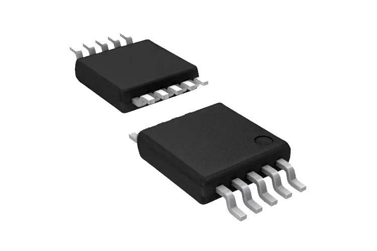
- Small µMAX Package
- Other Single Cell Chargers
Other Single Cell Chargers
TP5000, TP5100 module, TP4056, MCP73831
Note: Complete technical details can be found in the MAX1898 datasheet at this page’s end.
How To Use MAX1898?
The schematics below show the typical application diagram of a MAX1898. As mentioned earlier it only requires a very minimal number of components. That includes the current programming resistor, status led, and filter capacitors.
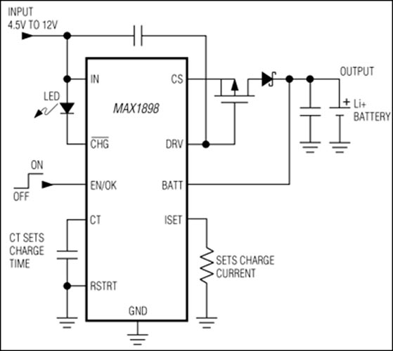
The MAX1898 regulates charging current by linearly controlling an external PMOS or PNP transistor. The maximum charging current is programmed by an external RSET resistor connected from ISET to GND. Select the RSET value based on the following formula:
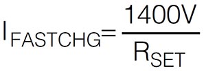
where: IFASTCHG is in amps and RSET is in ohms.
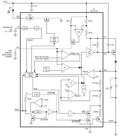
Functional Block Diagram
Applications
- Single-Cell Li+ Powered Portables
- Self-Charging Battery Packs
- PDAs
- Cell Phones
- Cradle Chargers
Absolute Maximum Ratings
- VDD: 7.0V
- All Inputs and Outputs w.r.t. VSS: -0.3 to (VDD+0.3)V
- Maximum Junction Temperature, TJ: Internally Limited
- Storage temperature: -65°C to +150°C
- ESD protection on all pins:
- Human Body Model (1.5kΩ in Series with 100pF): ≥ 4kV
- Machine Model (200pF, No Series Resistance): 400V
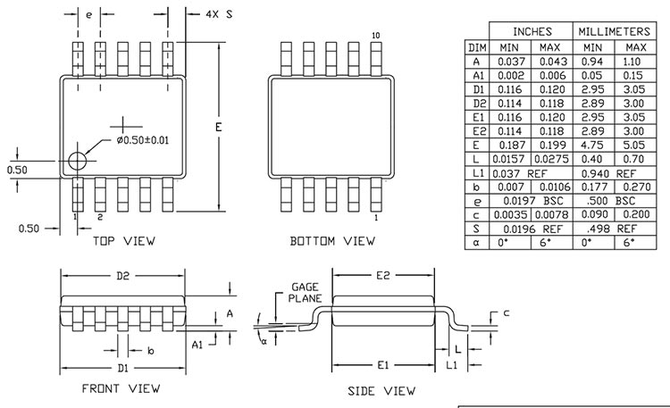
2D-Model and Dimensions