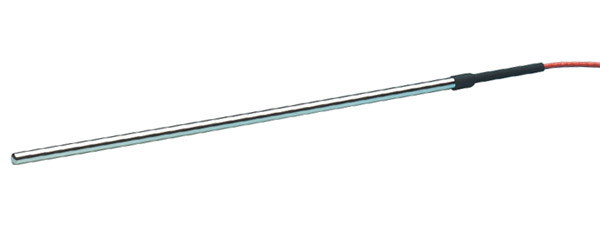
PT100 RTD Sensor

Pin Configuration
The PT100 sensor is just like a variable resistor, whose resistance varies with respect to the environment temperature. There are many types of PT100 sensors, the one we use here is a two wire one.
|
Pin Number |
Pin Name |
Description |
|
1 |
Pin 1 |
One end of the variable Resistor |
|
2 |
Pin 2 |
Other end of Variable Resistor |
Features
- Platinum Resistant Thermometer (PRT)
- Temperature Range: -200°C to 850°C
- Resistance Range: 1.849K to 39.026K
- Accuracy: ±0.1°C
- Nominal Resistance: 100Ω at 0°C
Note: Complete Technical Details can be found at the PT100 sensor datasheet given at the end of this page.
Alternative PRTs
PT100 (3-Wire), PT100 (4-Wire), PT500, PT1000
Alternative Temperature Sensors
LM35, DHT11, DHT22, Thermocouple, TMP100, LM75, DS18820, SHT15, LM35DZ, TPA81, D6T
Where to Use the PT100 Sensor?
The PT100 is a commonly used as industrial temperature sensor. It is known for its capability to measure high range temperature (200°C) with an accuracy of 0.1°C. The constriction of the sensor is also simple and hence it can be used in rugged environments. One downside of this sensor is that it will not work out of the box. To get useful values of temperature one should use it along with a potential divider or a Wheatstone bridge. But since these sensors just work with variable voltage it is very easy to use them in projects. So if you are looking for a sensor with good range and decent accuracy which is relatively cheap then PT100 would be a great choice.
How to Use PT100 Sensor?
The PT100 sensor falls under the category of PRTs (Platinum Resistant Thermometers). These sensors are nothing but a variable resistor which changes its resistance based on the temperature around it. So we need to build a small circuitry to measure the voltage across it. This circuitry can be as simple as a Potential divider or as complex as a Wheatstone bridge with Instrumentation amplifier. The design of the circuit depends on the accuracy needed for the project. Also there are many types of PT100, the one that we are discussing here is two wire sensors, and there are also sensors with 3-wires and even 4-wires. So to keep things simple let’s discuss how to interface a 2-wire sensor to a MCU using a simple potential divider circuit.
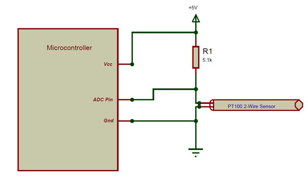
The PT100 sensor that we are designing for has a variable resistance from 1.8K to 39.02K as mentioned in the features above. So we have to convert this variable resistance value to a voltage value of 0V to 5V so that out microcontroller can understand it (here I am using a 5V MCU). To do this we have used a simple potential divider, according to the voltage divider calculator when the value of Input voltage is 5V and R1 is 5.1K and the PT100 resistance is 1.8K (minimum) we will get an output voltage of 1.304V and when the value of PT100 is 39.02K (maximum) we will get an output voltage of 4.42. Both the output voltages are in range for the microcontrollers ADC pin to read so we can proceed with the circuit. But for a circuit of this type the accuracy will be very less, if you require more accuracy you can dig deep into Wheatstone bridge and amplifiers.
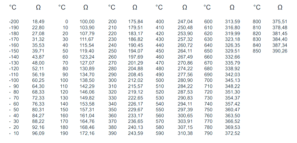
While calculating the value of resistance we also should consider the resistance of the wire, once the resistance value of the wire is known it will compensated with the actual value. More details on this can be found in datasheet below. Once you know the value of Resistance you can equate it to the value of temperature by using the below table-
Applications
- Measure high range Temperatures
- Rugged in construction hence can be used in harsh environments
- Measure duct temperatures
- Can measure a wide range of temperature with decent accuracy
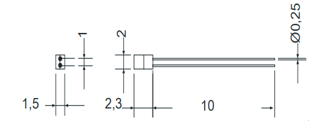
2D – Model