A3144 Hall Effect Sensor Module
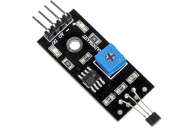
A3144 hall effect sensor module is used to detect the presence of a magnetic field. The output of the module goes high in the presence of a magnetic field and it becomes low in the absence of a magnetic field. The sensitivity of the sensor can be adjusted using a potentiometer.
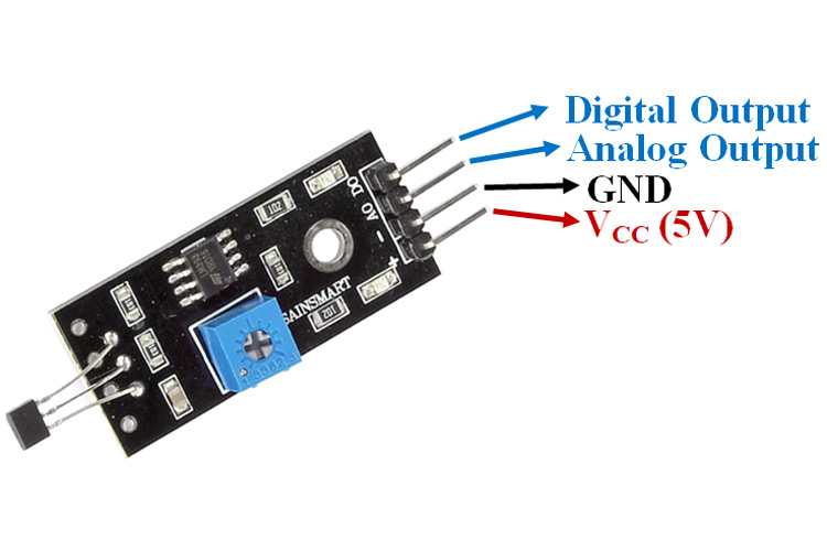
Pin Configuration of Hall Effect Sensor Module
|
Pin Name |
Description |
|
VCC |
The Vcc pin powers the module, typically with +5V |
|
GND |
Power Supply Ground |
|
DO |
Digital Output Pin. Directly connected to digital pin of Microcontroller |
|
AO |
Analog Output Pin. Directly connected to an analog pin of Microcontroller |
Hall Effect Sensor Module Features & Specifications
- Operating Voltage: 5V DC
- Digital Output 0V or 5V direct interface to a microcontroller with LED indication
- Sensor: Allegro A3144 Hall-effect switch
- LM393 comparator with threshold preset
- PCB Size: 32x12mm
- Detector type: Magnetic Sensing Hall effect
- Detecting range: 7 mm LM393 based design
- Easy to use with Microcontrollers or even with normal Digital/Analog IC
- Small, cheap and easily available
Alternate Sensor Modules: IR Sensor Module, TP4056ALi-ion Battery Charging/Discharging Module, DS3231 RTC Module, TMC2209 Stepper Motor Driver Module, DRV8825 Stepper Motor Driver Module, A4988 Stepper Motor Driver Module, NEO-6MV2 GPS Module, Joystick Module, EM18 - RFID Reader Module, ADXL335 Accelerometer Module, HMC5883L Magnetometer Module, Soil Moisture Sensor
Related Components: LM393 Comparator IC, 10K Potentiometer, Capacitor, Resistor
Brief about Hall Effect Sensor Module
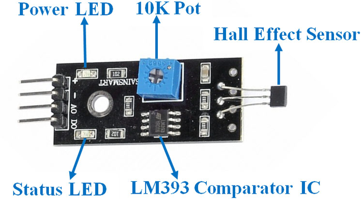
This Hall Effect Sensor Module consists of a Hall Sensor, resistors, capacitor, potentiometer, comparator LM393 IC, Power, and status LED in an integrated circuit.
LM393 IC
LM393 Comparator IC is used as a voltage comparator in this Hall Effect Sensor Module. Pin 2 of LM393 is connected to Preset (10KΩ Pot) while pin 3 is connected to the Hall Effect sensor. The comparator IC will compare the threshold voltage set using the preset (pin2) and the Hall Effect sensor pin (pin3).
Hall Effect Sensor
A3144 Hall Effect sensor provides a magnetic sensing solution with superior sensitivity stability over temperature and integrated protection features. These Magnetic sensors are designed to respond to a wide range of positive and negative magnetic fields
Preset (Trimmer pot)
Using the onboard preset, you can adjust the threshold (sensitivity) of the digital output.
How to Use the Hall Effect Sensor Module
Hall Effect Sensor Module consists of four pins i.e. VCC, GND, DO, AO. The digital output pin is connected to the output pin of the LM393 comparator IC while the Analog pin is connected to the Hall Effect sensor. The internal Circuit diagram of the Hall Effect Sensor Module is given below.
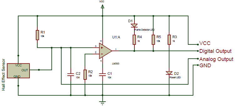
Using the Hall Effect sensor module with a microcontroller is very easy. Connect the Analog/Digital Output pin of the module to the Analog/Digital pin of Microcontroller. Connect VCC and GND pins to 5V and GND pins of Microcontroller.
Applications of Hall Effect Sensor Module
- Docking Detection
- Door Open and Close Detection
- Proximity Sensing
- Valve Positioning
- Pulse Counting


