EM18 - RFID Reader Module
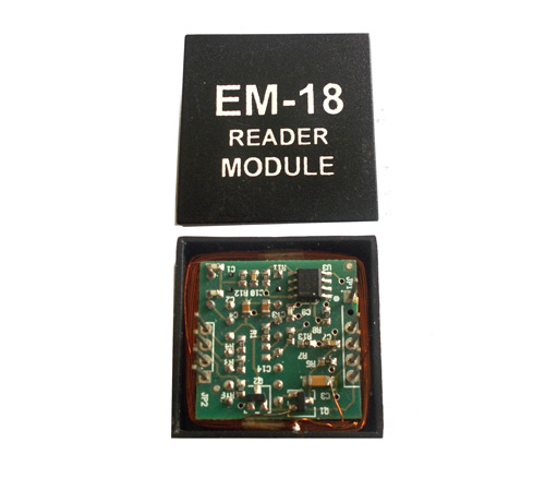
EM18 RFID Reader is a module which reads the ID information stored in RFID TAGS. This ID information is unique for every TAG which cannot be copied.
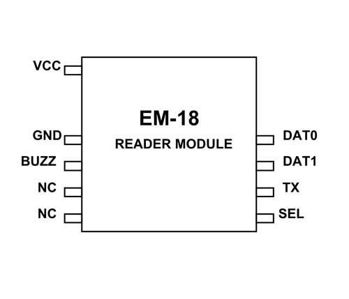
EM-18 Pin Configuration
EM-18 is a nine pin device. Among nine pins, 2 pins are not connected, so we basically have to consider seven terminals.
|
Pin Number |
Description |
|
VCC |
Should be connected to positive of power source. |
|
GND |
Should be connected to ground. |
|
BUZZ |
Should be connected to BUZZER |
|
NC |
No Connection |
|
NC |
No Connection |
|
SEL |
SEL=1 then o/p =RS232 SEL=0then o/p=WEIGAND |
|
TX |
DATA is given out through TX of RS232 |
|
DATA1 |
WEIGAND interface DATA HIGH pin |
|
DATA0 |
WEIGAND interface DATA LOW pin |
EM-18 Features and Specifications
- Operating voltage of EM-18: +4.5V to +5.5V
- Current consumption:50mA
- Can operate on LOW power
- Operating temperature: 0ºC to +80ºC
- Operating frequency:125KHz
- Communication parameter:9600bps
- Reading distance: 10cm, depending on TAG
- Integrated Antenna
Note: Complete technical details can be found in the EM-18 Datasheet linked at the bottom of this page.
Similar RFID reader modules
RMD6300, RC522
How to Use EM-18 RFID Module
EM-18 is used like any other sensor module. First we choose the mode of communication between MODULE and CONTROLLER. Next we will program the controller to receive data from module to display. Next power the system. When a tag is brought near the MODULE it reads the ID and sends the information to controller. The controller receives the information and performs action programmed by us.
Step1: Establishing a mode of communication. EM-18 can provide ouput through two communication interface. One is RS232 and another is WEIGAND. The form of communication is selected by SEL pin. If SEL pin is selected HIGH then form of communication is RS232 and if SEL pin is pulled LOW then form of communication is WEIGAND. Usually the RS232 is selected because it’s popular so SEL pin is pulled HIGH.
Step2: The output of MODULE bit rate is 9600bps (bit per second). The controller should be programmed to receive information from MODULE at this rate. If bit rate of controller mismatches then the system will not work correctly.
Now let us consider a simple EM-18 circuit diagram,
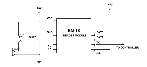
In the circuit BUZZER is not compulsory. When a TAG is read the BUZZER turns ON. As given in circuit, TX is given to CONTROLLER which is to receive DATA.
Consider a TAG is brought near the MODULE. The MODULE reads the ID and sends the information to controller in 12 ASCII CHARACTERS. In them, 10CHARACTERS represent the TAG ID and 2 CHARACTERS are XOR of previous 10 CHARACTERS.
So DATA sent = 10ASCII DATA (tag no.) + 2ASCII DATA (XOR result)
Once the Information is sent, the MODULES stop sending DATA. This serial DATA received by the controller though RX pin contains TAG information which is ready for processing. We can program the controller to save the DATA or process it to provide response immediately.
Applications
- Robotics
- Security systems
- Medical tags
- Computer Peripherals
- Package Identification
- Theft protection systems
- Data authorization
- Unique Identity
- Body implants
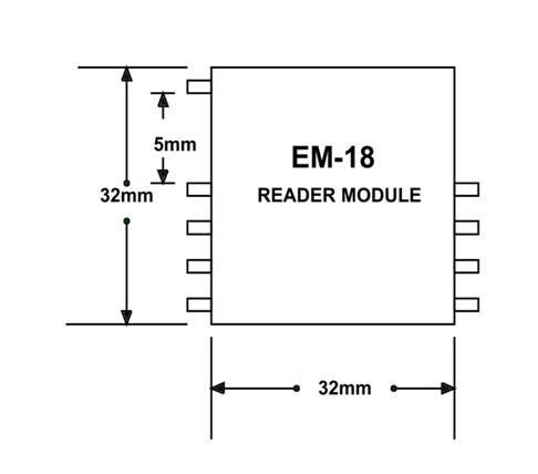
2D-Model
Measurements in millimeter (inches)