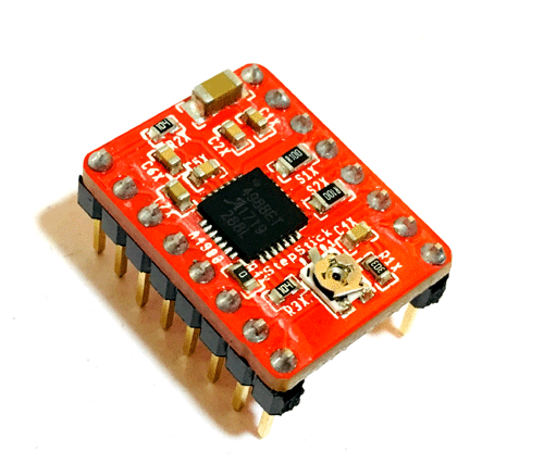
A4988 Stepper Motor Driver Module
The A4988 is a complete Microstepping Motor Driver with built-in translator for easy operation. The driver has a maximum output capacity of 35 V and ± 2 A. It can operate bipolar stepper motors in full-, half-, quarter-, eighth-, and sixteenth-step modes.
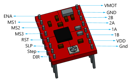
Pin Configuration
|
Pin Name |
Description |
|
VDD & GND |
Connected to 5V and GND of Controller |
|
VMOT & GND |
Used to power the motor |
|
1A, 1B, 2A, 2B |
Connected to the 4 coils of motor |
|
DIRECTION |
Motor Direction Control pin |
|
STEP |
Steps Control Pin |
|
MS1, MS2, MS3 |
Microstep Selection Pins |
|
SLEEP |
Pins For Controlling Power States |
|
RESET |
|
|
ENABLE |
A4988 Stepper Driver Module Features
- Max. Operating Voltage: 35V
- Min. Operating Voltage: 8V
- Max. Current Per Phase: 2A
- Microstep resolution: Full step, ½ step, ¼ step, 1/8 and 1/16 step
- Reverse voltage protection: No
- Dimensions: 15.5 × 20.5 mm (0.6″ × 0.8″)
- Short-to-ground and shorted-load protection
- Low RDS(ON) outputs
- Thermal shutdown circuitry
Alternatives for A4988: DRV8825, L6474, L6207, L6208, TMC2208, TMC2209
Note: Complete Technical Details can be found at the A4988 datasheet given at the end of this page.
How to Use A4988 Driver Module
As mentioned earlier A4988 has an inbuilt translator, so only two wires are required to connect it to controller board. Circuit Diagram for interfacing A4988 module with a microcontroller to control a stepper motor is shown below.
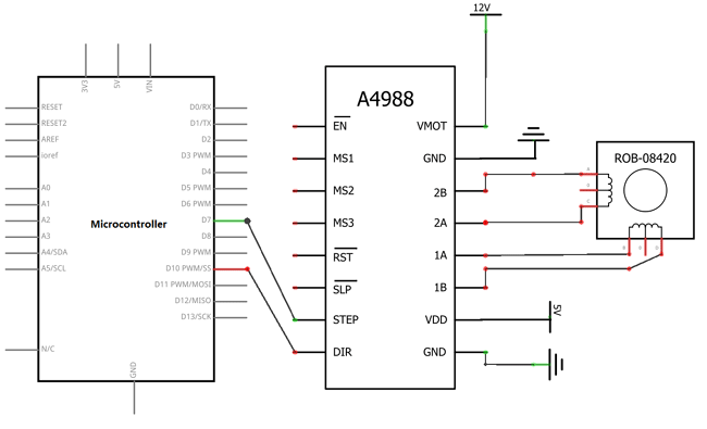
As shown in above diagram only two pins DIR and STEP of module is connected with Arduino. STEP pin used to control the steps while DIR pin is used to control direction. Micro-step pins (MS1, MS2 and MS3) are used to operate the driver module in different step functions. In the above circuit MS1, MS2, and MS3 pins left disconnected, that means the driver will operate in full-step mode. This motor driver has low-ESR ceramic capacitors on board, which makes it vulnerable to voltage spikes, so it is advised to use at least 47µf capacitor across motor power supply pins. Stepper Motor wires is connected with output pins (1A, 1B, 2A & 2B) of driver module. It is commonly used in controlling the NEMA series stepper motors like NEMA17, NEMA23, and NEMA34
Applications
- Used to control the speed and rotation of stepper motor.
- It is used in robotics to control their motion.
- It is used in different toys.
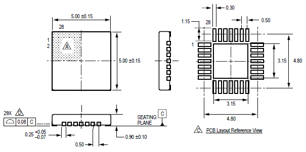
A4988 IC 2D-Model