IR Sensor Module
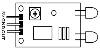
IR Sensor Module Pinout Configuration
|
Pin Name |
Description |
|
VCC |
Power Supply Input |
|
GND |
Power Supply Ground |
|
OUT |
Active High Output |
IR Sensor Module Features
-
5VDC Operating voltage
-
I/O pins are 5V and 3.3V compliant
-
Range: Up to 20cm
-
Adjustable Sensing range
-
Built-in Ambient Light Sensor
-
20mA supply current
-
Mounting hole
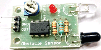
Brief about IR Sensor Module
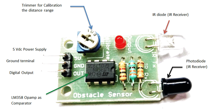
The IR sensor module consists mainly of the IR Transmitter and Receiver, Op-amp, Variable Resistor (Trimmer pot), output LED along with few resistors.
IR LED Transmitter
IR LED emits light, in the range of Infrared frequency. IR light is invisible to us as its wavelength (700nm – 1mm) is much higher than the visible light range. IR LEDs have light emitting angle of approx. 20-60 degree and range of approx. few centimeters to several feets, it depends upon the type of IR transmitter and the manufacturer. Some transmitters have the range in kilometers. IR LED white or transparent in colour, so it can give out amount of maximum light.
Photodiode Receiver
Photodiode acts as the IR receiver as its conducts when light falls on it. Photodiode is a semiconductor which has a P-N junction, operated in Reverse Bias, means it start conducting the current in reverse direction when Light falls on it, and the amount of current flow is proportional to the amount of Light. This property makes it useful for IR detection. Photodiode looks like a LED, with a black colour coating on its outer side, Black colour absorbs the highest amount of light.
LM358 Opamp
LM358 is an Operational Amplifier (Op-Amp) is used as voltage comparator in the IR sensor. the comparator will compare the threshold voltage set using the preset (pin2) and the photodiode’s series resistor voltage (pin3).
Photodiode’s series resistor voltage drop > Threshold voltage = Opamp output is High
Photodiode’s series resistor voltage drop < Threshold voltage = Opamp output is Low
When Opamp's output is high the LED at the Opamp output terminal turns ON (Indicating the detection of Object).
Variable Resistor
The variable resistor used here is a preset. It is used to calibrate the distance range at which object should be detected.
How to Use IR Sensor Module?
The 5 VDC supply input is given to the VCC pin and the supply negative is connected to the GND terminal of the module. When no object is detected within the range of the IR receiver, the output LED remains off.
When a object is detected within the range of the IR sensor the LED glows.
Applications
- Obstacle Detection
- Industrial safety devices
- Wheel encoder
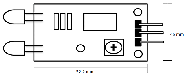
2D-Model