MP6513 bi-directional DC Motor Driver
The MP6513 is an H-bridge motor driver manufactured by Monolithic Power Systems. It can drive a DC motor, a winding of a stepper motor, or other such type of loads. The integrated H-bridge consists of four low RDSon N-channel power MOSFETs. The voltage required for the gate drivers is generated using an internal charge pump. The direction of rotation, breaking, and standby modes can be controlled using the two control pins. The MP6513 can be powered from a wide range of power supply voltage ranging from 2.5V to 21V. The maximum current the MP6513 can deliver is up to 800mA. The two control pins can achieve very low standby circuit current. The MP6513 also comes with several protection features that include over-current protection, short-circuit protection, under-voltage lockout (UVLO), and overtemperature protection. One other advantage of MP6513 is that it only requires a bare minimum number of readily available, standard, external components. The MP6513 is available in a TSOT23-6 package.
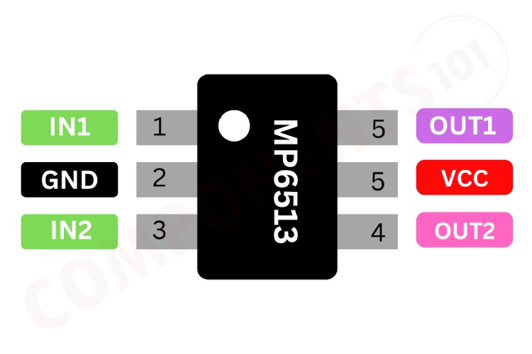
MP6513 Pinout Configuration
Here are the pinout details for MP6513.
| Number | Name | Description |
| 1 | IN1 | Input signal |
| 2 | GND | Ground |
| 3 | IN2 | Input signal |
| 4 | OUT2 | Motor terminal 2 |
| 5 | VCC | Supply voltage |
| 6 | OUT1 | Motor terminal 1 |
Features of MP6513
MP6513 bi-directional DC motor Driver has the following key features:
- Wide 2.5V to 21V Operating Input Range 0.8A Maximum Output Current
- Low MOSFET On Resistance (HS: 500mΩ; LS: 500mΩ)
- Easy to control using two logic level control pins.
- Internal charge pump for Mosfet driver
- Cycle-by-Cycle Over-Current Protection (OCP)
- Short-Circuit Protection (SCP)
- Thermal Shutdown
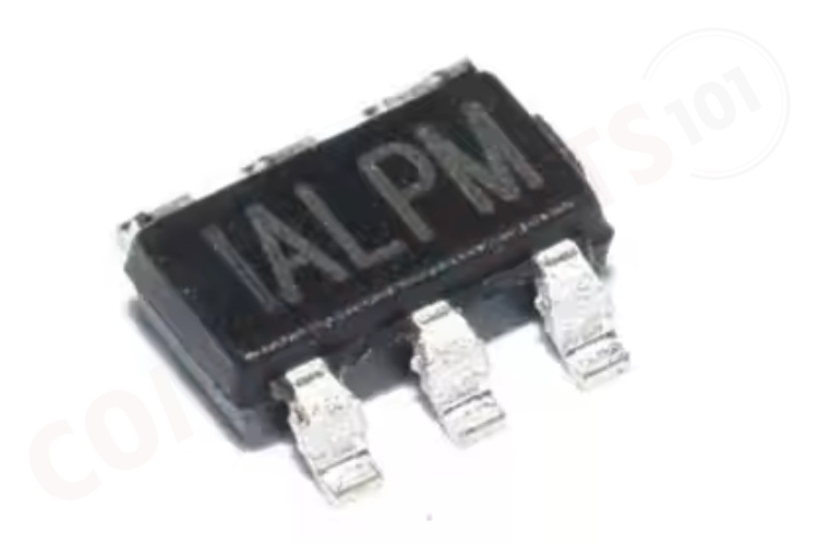
- Available in a TSOT23-6 Package
Manufacturers of MP6513:
The MP6513 is manufactured by Monolithic Power Systems. There are no alternative manufacturers for the same part number as of the date of writing this article.
MP6513 Equivalents
There are no pin-to-pin compatible Equivalents for MP6513 we could find.
MP6513 Alternatives
If you are looking for an alternative for MP6513 you can look at the other ICs from these.
L293D, L298, TB6612FNG, DRV8833, MAX1508, DRV8837, MAX1919, L9110, TA6586, A3908
Note: Complete technical details can be found in the MP6513 datasheet at this page’s end.
MP6513 Schematics
The following image shows the typical circuit diagram for MP6513.
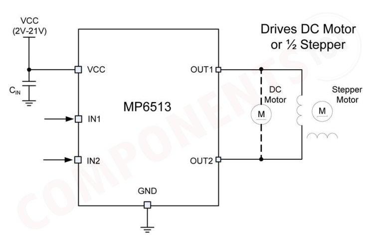
The circuit can be powered from a voltage source ranging from 2V to 21V connected to the VCC pin of the MP6513. A capacitor CIN is connected between the VCC and the ground to filter out noise from the power supply. IN1 and IN2 are the control input pins. They determine the state of the outputs OUT1 and OUT2, which in turn control the motor. These inputs are typically driven by a microcontroller or other control circuitry. The GND pin is connected to the ground of the power supply and the control circuitry. The OUT1 and OUT2 pins are connected to the motor. Depending on the states of IN1 and IN2, these outputs can drive current through the motor in either direction, allowing for bidirectional control of the motor. The motor can be either a DC motor or a stepper motor (1/2 stepper. For a DC motor, the motor is connected between OUT1 and OUT2. The MP6513 uses the states of IN1 and IN2 to control the H-bridge inside the IC, which directs the current flow through the motor. By changing the logic levels on IN1 and IN2, you can make the motor spin forward, backward, or stop. You can check the following truth table for the control logic.
| IN1 | IN2 | OUT1 | OUT2 | Function (DC Motor) |
| L | L | Z | Z | Coast / Standby |
| L | H | L | H | Reverse |
| H | L | H | L | Forward |
| H | H | L | L | Brake |
L indicates logic 0 and H indicates logic 1. Z stands for high impedance state.
Having Trouble with MP6513?
Is my circuit resetting when I turn on the circuit?
It might be due to the voltage spike/load drawing more current than the rated range, we can solve this by adding a capacitor parallel to supply voltage and also try to add a capacitor parallel with the motor.
What is the max voltage permissible on the MP6513 IN1 and IN2 pins when Vcc is 3.3V?
The absolute maximum voltage for these pins is 6V, but for safety, it is not recommended to go more than 5V.
Why my circuit is not working, the motor is not rotating?
Check all connections, and make sure everything is connected properly. Make sure the control pins are in appropriate states. Also, make sure the voltage and current ratings of the motor is within the limit of the driver IC.
The motor is jerking, why is that?
Make sure the voltage and current rating of the motor match with the IC maximum parameters. Add a .1uf capacitor parallel to the motor pins to reduce the noise.
How to interface an MP6513 with an Arduino?
For controlling the MP6513 you will need two GPIO pins. Connect the inputs of MP6513 to these pins, set them as output and by changing the state of these pins you can control the MP6513, and the motor connected to it. You can refer to the truth table given above.
Is a heat sink necessary for the working of MP6513?
It will depend on the maximum load that the driver needs to drive. If you are driving the chip at its maximum capability it is recommended to use a small heatsink if the chip gets hot. Use the equation provided in the next section to calculate the maximum power dissipation.
Design Choices to be Considered with MP6513
The recommended maximum junction temperature is 125°C under normal operating conditions. To ensure that the junction temperature is within this limit, calculate the maximum allowable dissipation (PD(MAX)) with Equation:
PD(MAX) = (TJ(max) - TA) / θJA (1)
Where TJ(max) is the maximum recommended operation junction temperature (125°C), θJA is the junction-to-ambient thermal resistance, and TA is the ambient temperature
Package
θJA (°C/W) Dissipation Power Rating
TA = 25°C TA = 50°C TA = 85°C
TSOT23-6 110 0.9W 0.65W 0.35W
Applications of MP6513
- Portable printers/scanners
- Camera lens/shutter control
- Battery powered toys and games
- Consumer Products
- Medical Devices
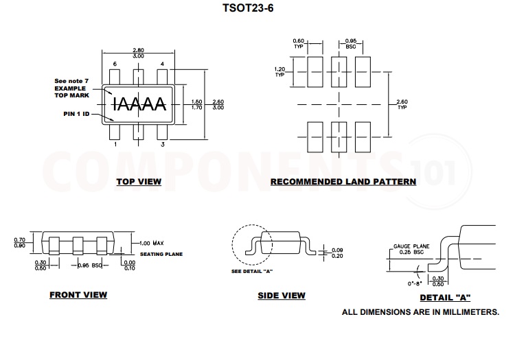
2D Model and Dimensions of MP6513
Here you can find the mechanical drawings of MP6513 along with its dimensions. The dimensions can be used to create custom footprints of the IC and be used for PCB or CAD modelling.