L9110 BI- Directional Motor Driver
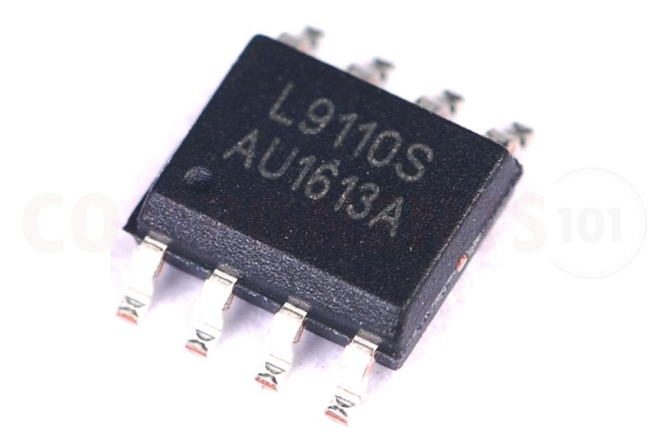

L9110 is a cheap bi-directional DC motor driver IC with a wide input voltage range. It has two inputs to control the direction of the motor. These inputs are TTL/CMOS compatible. This motor driver IC can provide 750-800mA continuous current and 1.5-2A peak current for loads. We can control relays, and DC motors with this IC without using any other electronic components. It has an inbuilt clamp diode, which will prevent the reverse inductive load current. This is suitable for controlling hobby projects and other motor-operated circuits. The L9110 is available in an 8-pin DIP and SOP8 package.
L9110 Pinout Configuration
Here are the pinout details for the L9110S motor driver.
| S. No | Name | Function |
| 1 | OA | A output pin |
| 2 | VCC | Supply Voltage |
| 3 | VCC | Supply Voltage |
| 4 | OB | B output pin |
| 5 | GND | Ground |
| 6 | IA | A input pin |
| 7 | IB | B input pin |
| 8 | GND | Ground |
Features of L9110
L9110 bi-directional DC motor Driver has the following key features.
- Low quiescent current
- Wide supply voltage range: 2.5V-12V
- 800mA continuous current output capability per channel
- Lower saturation voltage
- TTL / CMOS output level compatible, and can be directly connected to the CPU
- Output built-in clamp diodes for inductive load
- Integrated control and drive into a monolithic IC
- Pin high-voltage protection function
- Operating temperature: 0 ℃ -80 ℃.
Manufacturers of L9110 driver:
The L9110 motor driver chip is manufactured by many Asian manufacturers such as:
UMW (Youtai Semiconductor Co., Ltd.), HTCSEMI, JSMSEMI, Mixic, LANKE, Wuxi I-core Elec, HANSCHIP semiconductor, MSKSEMI, HXY MOSFET, HGSEMI, Wuxi I-core Elec, and XBLW.
There are no alternative manufacturers for the same part number as of the date of writing this article.
L9110 Equivalents
There is no pin-to-pin compatible equivalent available for L9110.
L9110 Alternatives
If you are looking for an alternative for L9110 you can look at the other ICs from these.
L293D, L298, TB6612FNG, DRV8833, MAX1508, TA6586, DRV8837, DRV8871, MX1919
Note: Complete technical details can be found in the L9110 datasheet at this page’s end.
L9110 Circuit Diagram
The following image shows the typical circuit diagram for the L9110 motor driver.
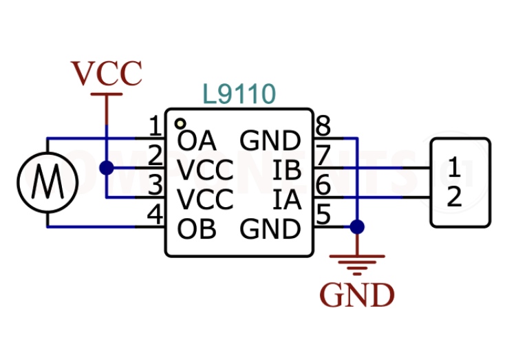
The above circuit diagram shows how to connect and drive a motor using L9110. In this circuit, the motor is connected to pins 1 and 4. All the grounds are connected to the ground of the circuit commonly. Also, the two supply pins are connected together and should connect to supply voltage. We have two inputs to control the motor in two directions, we connect these input pins to any microcontroller or logic circuits to control the IC. You can control the motor according to this truth table. There are no external components needed for the operation of this IC.
| IA | IB | OA | OB |
| H | L | H | L |
| L | H | L | H |
| L | L | L | L |
| H | H | L | L |
Problems with L9110 Circuit?
My circuit is resetting when I turn on the circuit?
It might be due to the voltage spike/load drawing more current than the rated range, so check the motor supply voltage and also try to add a capacitor parallel to the motor.
What check with an L9110 circuit, when it's not working?
1. Check all connections, and make sure everything is connected properly.
2. Check the motor voltage and current. Make sure that the rating is in the range of IC rating.
The IC gets very hot and automatically turns off:
- Overloading: The motor driver IC may be driving a motor that draws more current than the IC can handle. Check the datasheet for the maximum current rating of the motor
- Voltage Spikes: If there are voltage spikes or transients in the motor circuit, it could cause the IC to overheat. Adding capacitors to suppress these spikes can help protect the IC.
- Poor Heat Dissipation: The IC may not be dissipating heat efficiently. Make sure the IC is operating below 100 degrees Celsius
- The motor is jerking: make sure the voltage and current rating of the motor match with the IC maximum parameters. Add .1uf capacitor parallel to the motor pins to reduce the noise.
How to do L9110 Arduino Interfacing?
For controlling the L9110 you will need two GPIO pins. Connect the inputs of L9110 to these pins, set them as output and by changing the state of these pins you can control the 9110 and the motor connected to it. You can refer to the truth table given above.
Is a heat sink necessary for the working of L9110?
No. For most applications, the L9110 can operate without a heat sink within its specified operating conditions.
Design Choices to be Considered with L9110
Reverse connection between power supply and ground
Reversely connecting the power supply of the circuit to the ground wire will cause damage to the circuit, and in severe cases, it will cause smoke from the plastic package. It can be considered to connect two power Schottky diodes in series to the positive terminal of the battery at the power supply end of the circuit to prevent circuit damage caused by the reverse connection of the battery. The maximum continuous current capability of the power Schottky diode must be greater than the continuous current of the motor stall, otherwise the Schottky diode will be damaged due to overheating. The reverse breakdown voltage of the power Schottky diode must be greater than the maximum power supply voltage. If the reverse breakdown voltage is too small, the Schottky diode will break down and burn out when the battery is reversed.
PCB Layout Consideration
Grounding: Proper grounding is crucial to minimize noise and interference. Use a solid ground plane.
Current Capacity: The motor driver can handle high currents, so make sure that tracks have enough width.
Decoupling Capacitors: Place decoupling capacitors close to the motor driver's power pins and connect them to the ground plane with short and wide track.
Signal Tracks: Keep signal tracks short and direct, especially for control signals to and from the microcontroller or other logic circuits.
Applications of L9110
- Robotics
- Printers
- Motorised Vehicles
- Toys
- Solar Tracking System
- DIY Projects
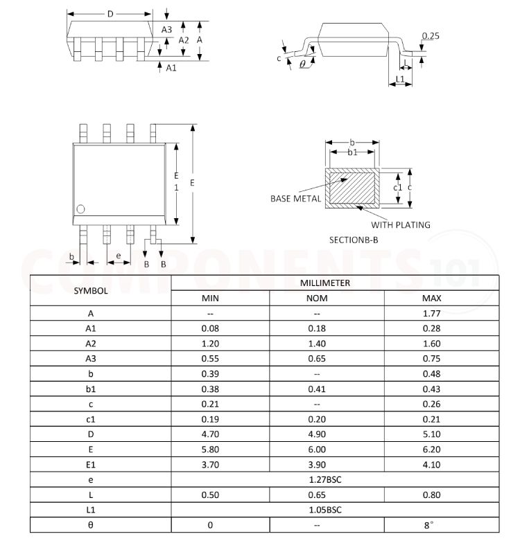
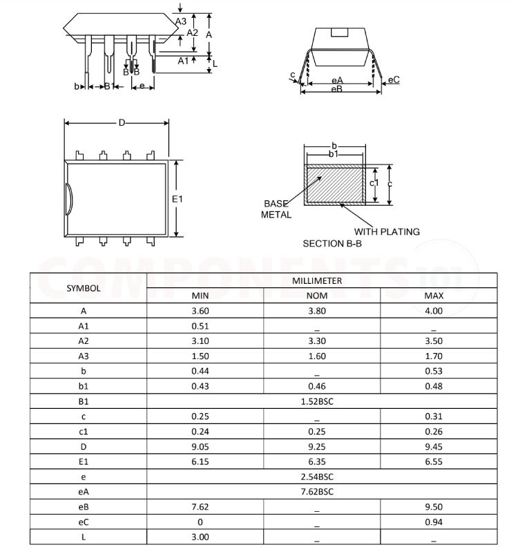
L9110 Footprint Information and Dimensions
Here you can find the mechanical drawings of L9110 along with its dimensions. The dimensions can be used to create a custom footprint of the chip and can be used for PCB or CAD modelling.