A3908 Bi-directional DC Motor Driver
The A3908 is a low-voltage bidirectional DC motor driver manufactured by Allegro Microsystems. The A3908 can be used to control the single motor in both directions. It has a typical input voltage range of 3 to 5.5 V, and it can deliver up to 500 mA current. A unique integrated full bridge ensures a constant voltage across the motor coil. The said full bridge driver stage uses low on-resistance FETs to reduce power dissipation and improve efficiency. The motor rotation direction and braking can be easily controlled with the given logic level control pins. The device also supports pulse-width modulation (PWM) control, which allows for precise speed control of the motor. This tiny IC comes with thermal shutdown, under-voltage lockout, and crossover current (shoot-through) protection. This IC is very useful in portable projects because of its small size. The A3908 is available in an 8-lead DFN package, with an exposed thermal pad. It can be ordered using the part number A3908EEETR-T.
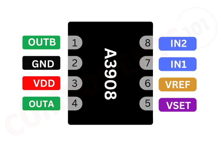
A3908 Pinout Configuration
Here are the pinout details for A3908.
| Number | Name | Description |
| 1 | OUTB | Motor terminal |
| 2 | GND | Ground |
| 3 | VDD | Input supply |
| 4 | OUTA | Motor terminal |
| 5 | VSET | Select source-side output voltage |
| 6 | VREF | Bandgap reference |
| 7 | IN1 | Control logic input |
| 8 | IN2 | Control logic input |
Features of A3908
A3908 bi-directional DC motor Driver has the following key features:
- Constant voltage operation (adjustable)
- 500 mA output peak rating
- Low-power standby mode
- Small 2 mm×2mm, 0.55 mm nominal height DFN package
- Typical input voltage range of 3 to 5.5 V
- Adjustable constant voltage or PWM operation
- Less than 500 nA standby mode current
- –40°C to 85°C operating temperature range
Manufacturers of A3908:
The A3908 is manufactured by Allegro Microsystems. There are no alternative manufacturers for the same part number as of the date of writing this article.
A3908 Equivalents
If you are looking for pin-to-pin compatible equivalents for the A3908, you may use the A3903 from the same manufacturer.
A3908 Alternatives
If you are looking for an alternative for A3908 you can look at the other ICs from these.
L293D, L298, TB6612FNG, DRV8833, MAX1508, DRV8837, MAX1919, L9110, TA6586
Note: Complete technical details can be found in the A3908 datasheet at this page’s end.
A3908 Circuit Diagram
The following image shows the typical circuit diagram for A3908.
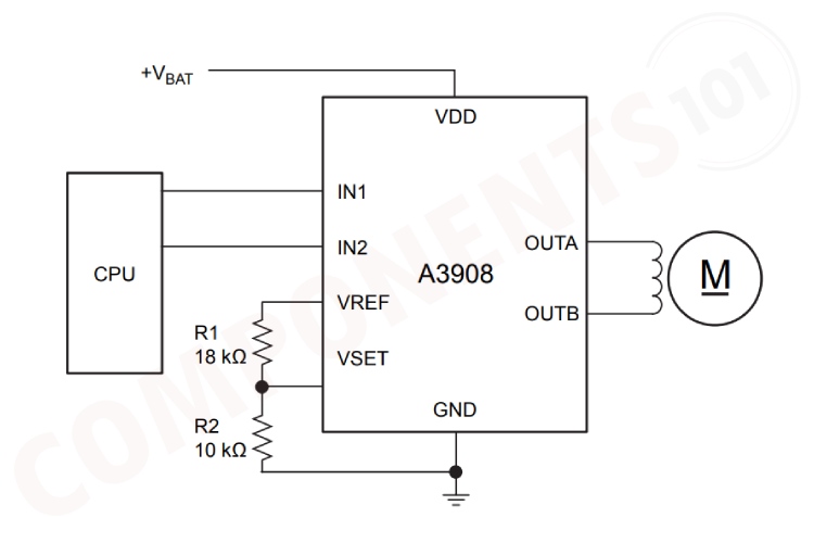
The above circuit diagram shows how to connect and drive a motor using A3908. In this circuit, the motor is connected to pin OUTA and pin OUTB. The input pins can be connected to any microcontroller circuit like Arduino, which sends signals to the A3908 motor driver to control the motor. The VREF pin is used to set the reference voltage for the motor driver, which helps in controlling the speed of the motor. The VSET pin is used to set the voltage threshold for the motor driver. The resistors R1 and R2 form a voltage divider network that sets this threshold voltage. The working of this circuit is as follows. The microcontroller sends control signals to the IN1 and IN2 pins of the A3908. Depending on the signals at IN1 and IN2, (see the truth table below) the A3908 controls the OUTA and OUTB outputs to drive the motor in the desired direction and speed. The speed and behavior of the motor can be further fine-tuned using the VREF and VSET pins.
| Settings | ||||
| IN1 | IN2 | OUTA | OUTB | Resulting Mode |
| 0 | 0 | Off | Off | Standby |
| 0 | 1 | Low | VREG | Reverse |
| 1 | 0 | VREG | Low | Forward |
| 1 | 1 | High | High | Brake |
Having Trouble with A3908?
My circuit is resetting when I turn on the circuit.
It might be due to the voltage spike/load drawing more current than the rated range; we can solve this by adding a capacitor parallel to supply voltage and also try to add a capacitor parallel with the motor.
Why is my circuit not working?
Check all connections, and make sure everything is connected properly. Also, make sure the control pins are in the correct state.
The motor is jerking, what would be the reason?
Make sure the voltage and current rating of the motor match with the IC maximum parameters. Add .1uf capacitor parallel to the motor pins to reduce the noise.
How to do A3908 Arduino Interfacing?
For controlling the A3908 you will need two GPIO pins. Connect the inputs of A3908 to these pins, set them as output and by changing the state of these pins you can control the A3908, and the motor connected to it. You can refer to the truth table given above.
Is a heat sink necessary for the working of A3908?
No. For most applications, the A3908 can operate without a heat sink within its specified operating conditions.
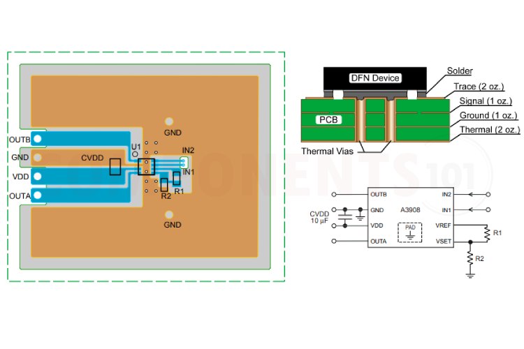
Design Choices to be Considered with A3908
The printed circuit board should use a heavy ground plane for optimum thermal performance. The A3908 must be soldered directly onto the board. On the underside of the A3908 package is an exposed pad, which provides a path for enhanced thermal dissipation. The thermal pad should be soldered directly to an exposed surface on the PCB. Thermal vias are used to transfer heat to other layers of the PCB. Thermal vias should not have any thermal relief and should be connected to internal layers, if available, to maximize the dissipation area.
In order to minimize the effects of ground bounce and offset issues, it is important to have a low-impedance, single-point ground, known as a star ground, located very close to the device. By making the connection between the exposed thermal pad and the ground plane directly under the A3908, that area becomes an ideal location for a star ground point. A low-impedance ground will prevent ground bounce during PWM operation and ensure that the supply voltage remains stable at the input terminal. Bulk capacitance is often located at a non-ideal distance from the device. If the recommended capacitance of 10 µF cannot be located very close to the supply terminal on the A3908, it is recommended that a 0.1 µF capacitor be placed as close to the VDD terminal as possible to provide a path for transient currents.
PWM Operation
In some applications, current control may be desired. Pulse width modulating the inputs will allow the output current to be regulated. When external PWM control is used, the VREF pin should be connected directly to the VSET pin. This effectively disables voltage control on the source driver and allows maximum current to flow through the driver. Current is then controlled using enable chopping, as described in the datasheet.
Applications of A3908
- Robotic actuators and pumps
- Portable printers/scanners
- Camera lens/shutter control
- Battery-powered toys and games
- Low noise test instrumentation systems
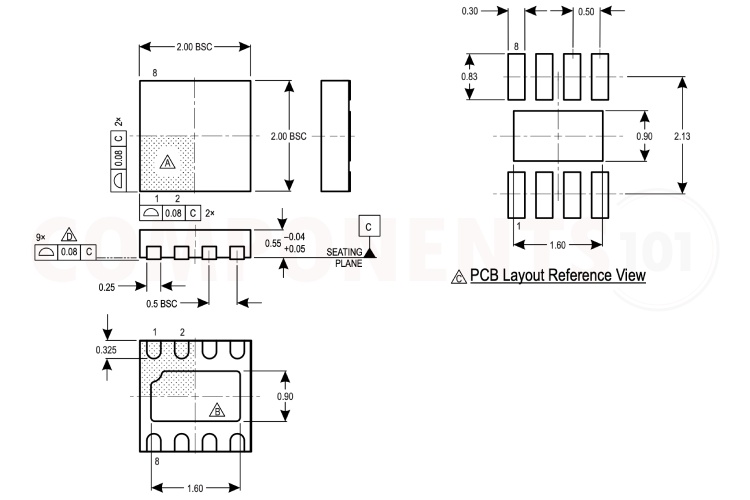
2D Model and Dimensions of A3908
Here you can find the mechanical drawings of A3908 along with its dimensions. The dimensions can be used to create custom footprints of the IC and be used for PCB or CAD modelling.