TB6612FNG Dual DC Motor Driver IC
TB6612FNG is a DC motor driver IC by Toshiba. This is an H-bridge motor controller that is used to control two DC motors. This driver IC can be used with any microcontrollers like Arduino, Raspberry PI, etc. TB6612FNG has dual-channel circuit output with a high current MOSFET H-bridge structure. This IC control DC motors with two input signals IN1 and IN2. By selecting input signals, the motor can be controlled in four modes; Clockwise (CW), Counter Clockwise (CCW), Short break and Stop mode.
The DC motor cannot be driven only with a microcontroller because the DC motor requires more current than the microcontroller. Hence, other hardware is required for DC motors with microcontrollers. TB6612FNG is an IC that is used to interface and control the DC motor with a microcontroller.TB6612FNG is a low-resistance inexpensive IC to control the speed and direction of DC motors. It is a dual-channel IC. That means, we can control two DC motors with one IC. It has two channels; channel-A and channel-B. The DC motors are connected with the output pins of IC.
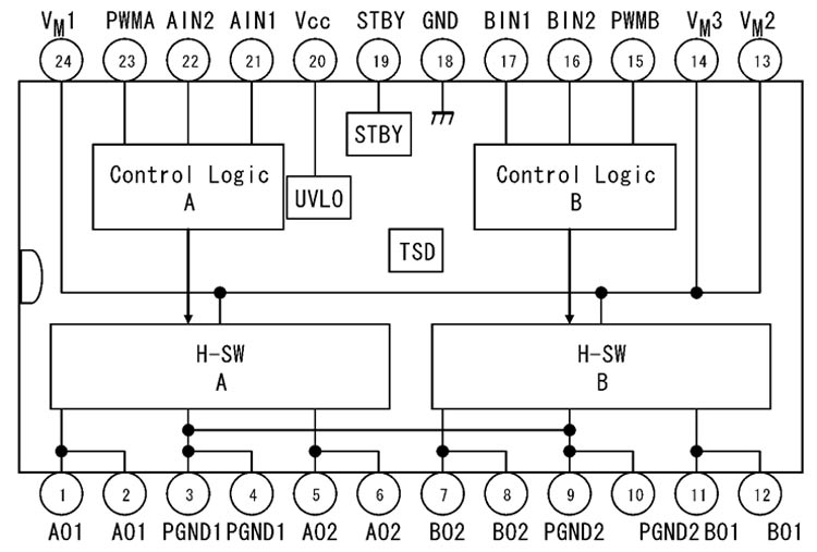
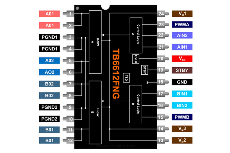
TB6612FNG IC Pinout Configuration
TB6612FNG has 24 pins and the function of each pin is shown in the table below.
|
Pin No |
Pin Name |
Pin Description |
|
1 |
AO1 |
Ch-A output 1 |
|
2 |
AO1 |
|
|
3 |
PGND1 |
Power Ground 1 |
|
4 |
PGND1 |
|
|
5 |
AO2 |
Ch-A output 2 |
|
6 |
AO2 |
|
|
7 |
BO2 |
Ch-B Output2 |
|
8 |
BO2 |
|
|
9 |
PGND2 |
Power Ground 2 |
|
10 |
PGND2 |
|
|
11 |
BO1 |
Ch-B Output 1 |
|
12 |
BO1 |
|
|
13 |
VM2 |
Motor Supply (2.5 V – 13.5 V) |
|
14 |
VM3 |
|
|
15 |
PWMB |
Ch-B PWM input |
|
16 |
BIN2 |
Ch-B input 2 |
|
17 |
BIN1 |
Ch-B input 1 |
|
18 |
GND |
Small signal ground |
|
19 |
STBY |
Standby |
|
20 |
VCC |
Small signal supply (2.7 V – 5.5 V) |
|
21 |
AIN1 |
Ch-A input 1 |
|
22 |
AIN2 |
Ch-A input 2 |
|
23 |
PWMA |
Ch-A PWM input |
|
24 |
VM1 |
Motor Supply (2.5 V – 13.5 V) |
Features & Specifications
- Supply Voltage VCC: 15V
- Output Voltage Vout: 15V
- Output Current Iout: 1.2A
- Peak Output Current (Continuous pulse, 20ms): 2A
- Peak Output Current (Single pulse, 10ms): 3.2A
- Power dissipation: 0.78W
- Operating temperature: -20 to 85˚C
TB6612FNG Equivalents
L298N, LV8406T
Note: More technical specifications about TB6612FNG IC can be found in the TB6612FNG IC datasheet attached at the end of this page.
Working of TB6612FNG Dual DC Motor Driver IC
This IC is used to control two DC motors. One motor is connected with pin AO1 and AO2 (Channel-A). The second motor is connected with pin BO1 and BO2 (Channel-B). According to input pins AIN1/AIN2 and BIN1/BIN2, the chip generates four PWM outputs that are used to control the motor in four operating modes.
|
Input-1 (AI1 or BI1) |
Input-2 (AI2 or BI2) |
Mode |
|
High |
High |
Short Brake |
|
Low |
Low |
Stop |
|
High |
Low |
Clockwise (CW) |
|
Low |
High |
Counterclockwise (CCW) |
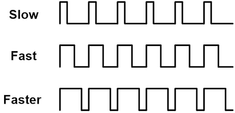
The speed of the motor is controlled by the input pin PWMA and PWMB. The duty cycle of the PWM signal will control the speed of the motor. The width of the pulse of the PWM signal decides the average value of output voltage that will decide the speed of the motor. When the motor is running, the STBY pin must be set to a high level. The effect of the PWM signal on the speed of the motor is shown in the figure below.
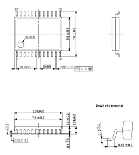
2D Model and Dimensions
If you are designing a PCB or Perf board with this component then the following picture from the Datasheet will be useful to know its package type and dimensions.