MAX8903 Dual Input 1-Cell Li Charger IC
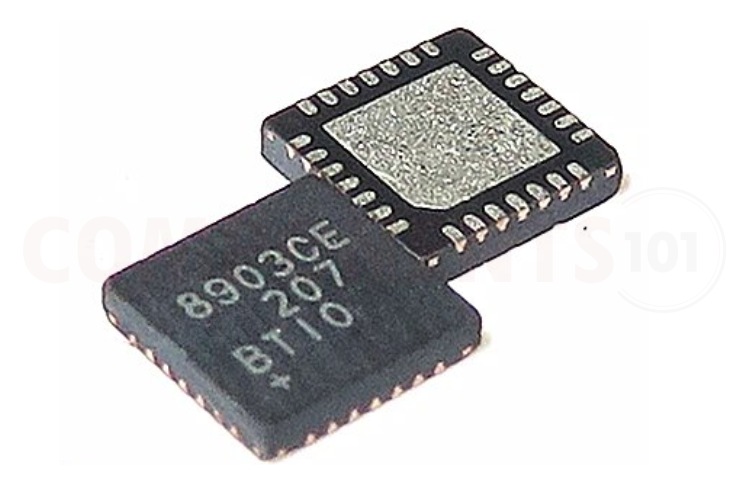
The MAX8903 is a dual-input charger which supports separate DC and USB inputs. This switch mode charger uses high-speed switching to eliminate heat and decrease external components. No external MOSFETs, blocking diodes, or current-sense resistors are required to work MAX8903. The MAX8903 has smart power control, making the IC best for USB or adapter power. Battery charge current can be set up to 2A while the USB input current can be set to 100mA or 500mA. The built-in step-down converter supplies up to 2A to the system, the battery, or a combination of both. A USB charge input can charge the battery and power the system from a USB power source. When powered from USB or the DC input, system load current peaks that exceed what can be supplied by the input are supplemented by the battery. The MAX8903 also features overvoltage protection, charge status and fault outputs, power-OK monitors, and a battery thermistor monitor. In addition, it has thermal limiting which reduces the battery charge current and prevents charger overheating. The MAX8903 is available in 28-pin thin QFN package.
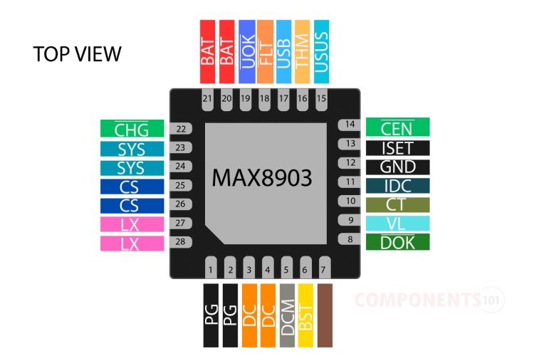
MAX8903 Pinout Configuration
Here are the pinout details for MAX8903.
| PIN | NAME | FUNCTION |
| 1, 2 | PG | Power Ground for Low-Side Synchronous MOSFET. |
| 3, 4 | DC | DC Power Input. |
| 5 | DCM | Current-Limit Mode Setting for the DC Power Input. |
| 6 | BST | High-Side MOSFET Driver Supply. |
| 7 | IUSB | USB Current-Limit Set Input. |
| 8 | DON | DC Power-OK Output. |
| 9 | VL | Logic LDO Output. |
| 10 | CT | Charge Timer Set Input. |
| 11 | IDC | DC Current-Limit Set Input. |
| 12 | GND | Ground. |
| 13 | ISET | Charge Current Set Input. |
| 14 | CEN | Charger Enable Input. |
| 15 | USUS | USB Suspend Input. |
| 16 | THM | Thermistor Input. |
| 17 | USB | USB Power Input. |
| 18 | FLT | Fault Output. |
| 19 | UON | USB Power-OK Output. |
| 20,21 | BAT | Battery Connection. |
| 22 | CHC | Charger Status Output. |
| 23, 24 | SYS | System Supply Output. |
| 25, 26 | CS | 70m Current-Sense Input. |
| 27, 28 | LX | Inductor Connection |
| — | EP | Exposed Pad. |
Manufacturers of MAX8903:
The MAX8903 is manufactured by Analog Devices (earlier this IC was from Maxim Integrated). There are no alternative manufacturers for the same part number as of the date of writing this article.
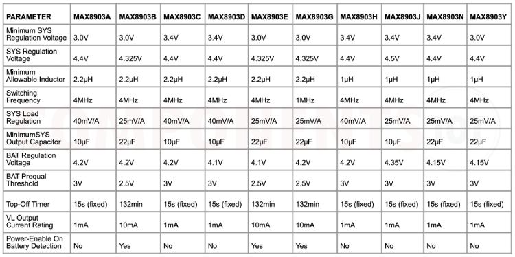
MAX8903 Partnumber Variants and Equivalents
If you are looking for an equivalent or replacement for MAX8903, we weren’t able to find any other chip that is pin-to-pin compatible. But you can find many multiple variants of MAX8903 with different charging characteristics. Please use the table below to find the best one appropriate for your usage. The MAX8903 IC has different part numbers such as MAX8903A, MAX8903B, MAX8903C, MAX8903D, MAX8903E, MAX8903G, MAX8903H, MAX8903J, MAX8903N, and MAX8903Y. While the basic function of all these variants remain same they have slightly different specifications which are highlighted below.
MAX8903 Alternatives
If you are looking for an alternative for MAX8903 you can look at the other IC from these.
BQ29700, MCP73831, TP5000, TP5100 module, TP4056, MAX1898, LTC4054, BQ24074, MAX1555
Note: Complete technical details can be found in the MAX8903 datasheet at this page’s end.
Features of MAX8903
MAX8903 CMOS Dual input single-cell lithium-ion battery charger has the following key features:
- Efficient DC-DC Converter Eliminates Heat
- 4MHz Switching for Tiny External Components
- Instant On—Works with No Battery or Low Battery
- Dual Current-Limiting Inputs—AC Adapter or USB
- Automatic Adapter/USB/Battery Switchover to Support Load Transients
- 50mΩ System-to-Battery Switch
- Supports USB Spec
- Thermistor Monitor
- Integrated Current-Sense Resistor
- No External MOSFETs or Diodes
- 4.1V to 16V Input Operating Voltage Range
- 2A maximum current
MAX8903 Schematics
The following image shows the typical circuit diagram for MAX1555.
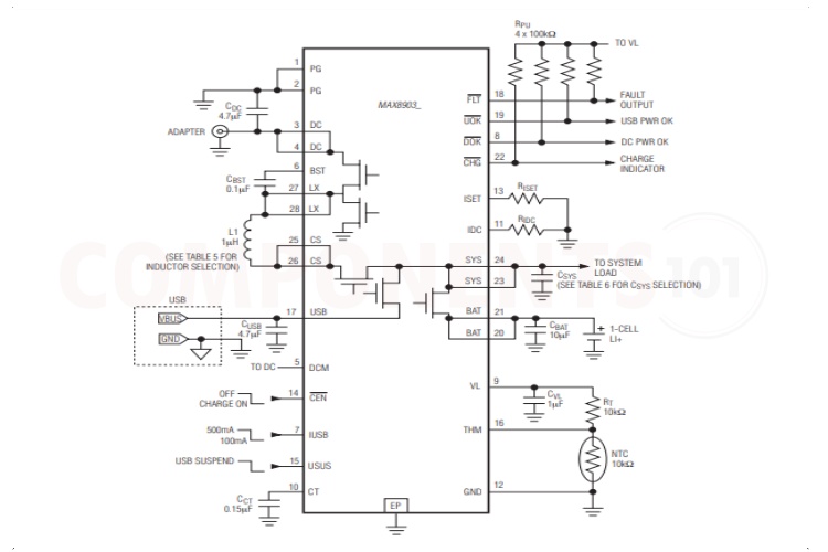
As you can see the number of external components required is very few. The inputs were connected to the respective pins with a smoothing capacitor attached to them. the switching inductor is connected between the LX and CS pins. The BST pin is bypassed to the Lx pin using a 100nF capacitor. Respective values of the resistor were connected to the Iset and IDc pins. The resistor connected to the Iset determines the charging current while the resistor connected to the IDC pin sets the DC current limit. Pull-up resistors were added to the status pins. Capacitors were added to the sys output and bat pins for smoother operations. A voltage divider formed with a 10 K resistor and an NTC is used for temperature monitoring.
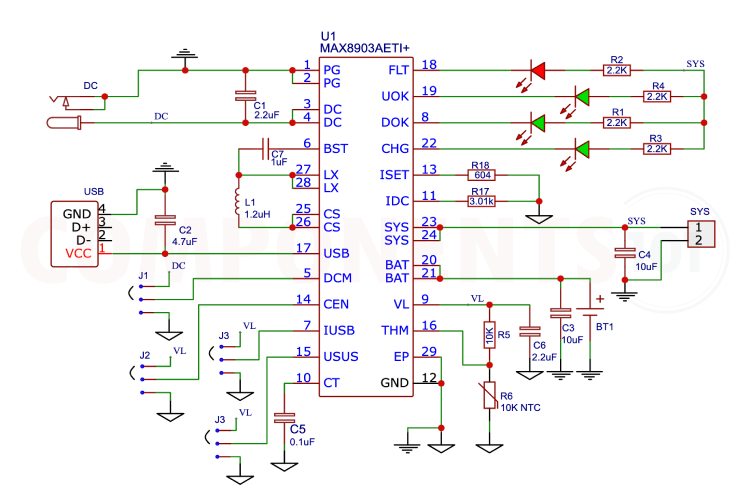
Here is a practical circuit diagram for a MAX8903 charger. Here we have added jumpers for the control pins for easy configuration, with this setup the circuit can be stand-alone. LEDs were connected to the status pin for easy indications. The fault status is connected to a red LED and all other status pins are connected to green LEDs.
MAX8903 Charger IC not Working?
- The battery is not charging: Check the connections properly, and check whether the grounds of the input supply and battery are properly connected to the ground pin of the IC. Also, make sure that the battery is not flat-out dead.
- The charging current is too low: Check the temperature of the IC, that is if the generated heat does not dissipate the charging current will be limited by the IC. Also with a USB input pin, the charging current is limited to 500mA. for the maximum charging current use, the DC input. The USB charge current can be switched between 100mA and 500mA using the IUSB pin. So, check connections to that pin.
- The circuit’s performance is not stable: DC Power Input. DC is capable of delivering up to 2A to SYS. DC supports both AC adapter and USB inputs. The DC current limit is set through DCM, IUSB, or IDC depending on the input source used. Both DC pins must be connected together externally. Connect at least a 4.7µF ceramic capacitor from DC to PG. Also, Connect a 4.7µF ceramic capacitor from USB to GND
Design Choices to be Considered with MAX8903
Is a heat sink necessary for the working of max8903?
No. For most applications, the MAX8903 can operate without a heat sink within its specified operating conditions.
Is it possible to charge more than one battery with MAX8903?
No, the MAX8903 is designed to charge single-cell lithium-ion/polymer batteries.
How to connect Thermistor to the IC?
Connect a negative temperature coefficient (NTC) thermistor from THM to GND. Connect a resistor equal to the thermistor +25°C resistance from THM to VL. Charging is suspended when the thermistor is outside the hot and cold limits. Connect THM to GND to disable the thermistor temperature sensor.
What is MAX8903AETI+T?
The MAX8903AETI+T is the a complete partnumber for the MAX8903 IC variant. The + denotes that the IC is Lead(Pb) free and RoHS-compliant and the T denotes its available in Tape and Reel package.
What are the design considerations when designing a PCB using MAX8903?
Good design minimizes ground bounce and voltage gradients in the ground plane, which can result in instability or regulation errors. The GND and PGs should connect to the power-ground plane at only one point to minimize the effects of power-ground currents. Battery ground should connect directly to the power-ground plane. The ISET and IDC current-setting resistors should connect directly to GND to avoid current errors. Connect GND to the exposed pad directly under the IC. Use multiple tightly spaced vias to the ground plane under the exposed pad to help cool the IC. Position input capacitors from DC, SYS, BAT, and USB to the power-ground plane as close as possible to the IC. Keep high current traces such as those to DC, SYS, and BAT as short and wide as possible. Refer to the MAX8903A Evaluation Kit for a suitable PCB layout example.
Applications of MAX8903
- PDAs
- Wireless Appliances
- Cell Phones
- Digital Cameras
- Personal Navigation Devices
- Portable Multimedia Players
- Mobile Internet Devices
- Ultra Mobile PC
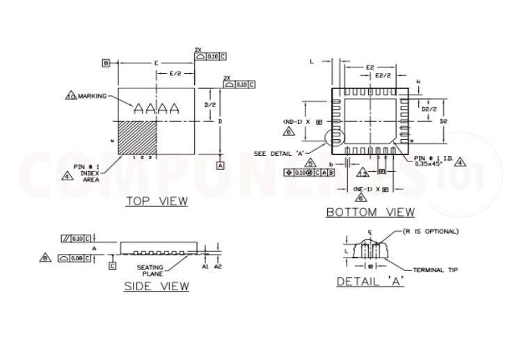
2D Model and Dimensions of MAX8903
Here you can find the mechanical drawings of MAX8903 along with its dimensions. The dimensions can be used to create custom footprints of the module and be used for PCB or CAD modelling.