HCPL0600 High Speed Optocoupler
The HCPL-0600 is a Single channel high-speed Optocoupler with open collector Schottky clamped transistor output. HCPL0600 consists of an AIGaAS LED optically coupled to a high-speed photodetector transistor.
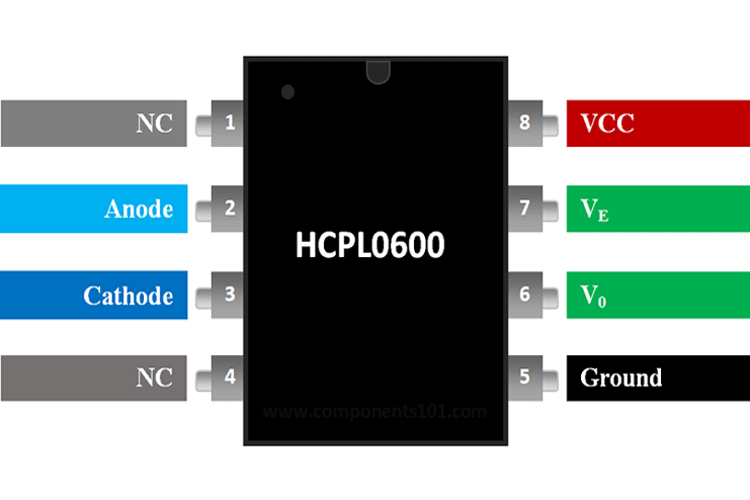
Pin Description 0f HCPL0600
|
Pin Number |
Pin Name |
Description |
|
1 |
NC |
No Connection |
|
2 |
Anode |
Anode pin of the IR LED. Connected to a logic input |
|
3 |
Cathode |
Cathode pin of the IR LED |
|
4 |
NC |
No Connection |
|
5 |
Ground |
Ground pin of the IC |
|
6 |
Output (V0) |
The isolated output pin of the Optocoupler |
|
7 |
Enable (VE) |
By default, it is enabled through a pull-up resistor. |
|
8 |
Vcc |
Powers the IC |
Features and Specifications HCPL0600
- High-Speed Optocoupler (10Mbit/s)
- Isolation Voltage: 3750Vrms
- Vf - Forward Voltage: 1.5V
- If - Forward Current: 10 mA
- Vr - Reverse Voltage: 5V
- Power Dissipation: 85 mW
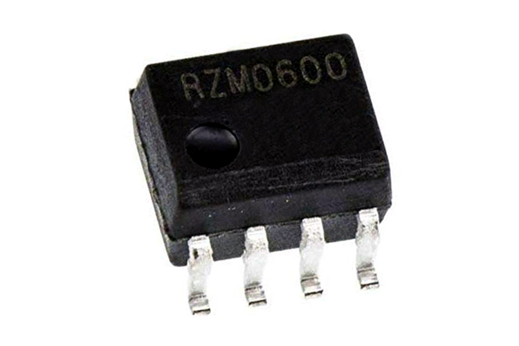
- Available in SO-8 Package
Note: More details can be found in the HCPL0600 datasheet which is available for download at the end of this page.
Equivalent for HCPL0600: 6N137
Alternatives Optocouplers: MOC3021 (Zero-crossing), MCT2E (non-Zero transistor), MOC3041 (Non-Zero Cross TRIAC), FOD3180 (High-Speed MOSFET), PC817, 4N25, 6N137
Where to use HCPL0600 Optocoupler
The HCPL0600 is a High-Speed Optocoupler or Optoisolator with a switching rate of 10Mbit/sec. The output of HCPL0600 is NAND gate logic with an open drain transistor as one input and Enable pin as another input.
The typical operating voltage of HCPL0600 is only 5V hence it cannot switch high loads and can also sink a maximum of only 7mA on its output side. Apart from that, the IC also has an Enable pin which comes in handy while designing a strobe circuit for your camera flash.
So if you are looking for a high-speed optocoupler for some digital applications like data conversion or noise elimination, then this IC might be the right choice for you.
How to use HCPL0600
An Application circuit from the HCPL0600 datasheet is given below. HCPL0600 is commonly used with Digital circuits with 5V supply voltage but it can work with both AC and DC.
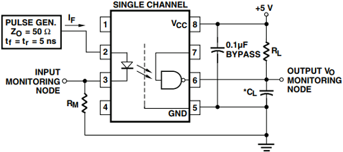
The Capacitor (0.1uF) connected across the Supply rail is a bypass capacitor. The input signal should have an impedance of a minimum of 50 ohms with rising time and falls of 5nS of greater for the IC to respond. The input signal can be probed (if required) on pin 3 and the pulldown resistor Rm is optional and can be used only if you are connecting the signal to scope.
As told earlier the output (pin 6) is an open-drain transistor and hence it can either sink current or remain floating. So, to avoid floating, we should use a pull-up resistor RL, the value of RL can be between 330 ohms to 4K depending upon the load connected.
The pin 7 is the Enable pin, this pin has an in-built pull-up resistor hence by default, the IC is enabled when powered. When connected to the ground, it will disable the output. The pin can be put into use to create strobe circuits, etc.
Applications of HCPL0600
- Camera Strode lights
- High-speed ADC and DAC
- Fibre/optic communication
- Noise isolation circuits
- Input/Output isolation circuits
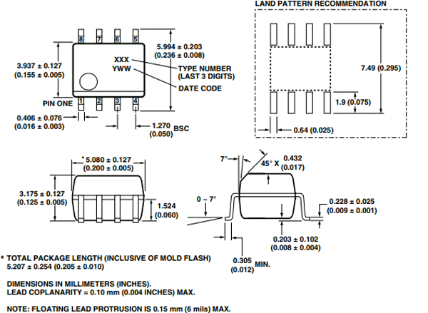
2-D Model of HCPL0600
Dimensions for HCPL0600 IC is given below.