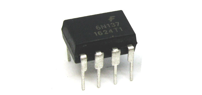
6N137 High Speed Optocoupler
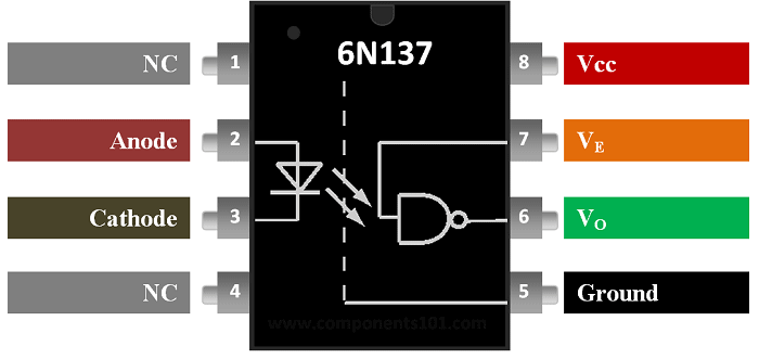
6N137 Pin Configuration
|
Pin No |
Pin Name |
Description |
|
1 |
NC |
No Connection - Cannot be used |
|
2 |
Anode (A) |
Anode pin of the IR LED. Connected to logic input |
|
3 |
Cathode (C) |
Cathode pin of the IR LED |
|
4 |
NC |
No Connection - Cannot be used |
|
5 |
Ground |
Ground pin of the IC |
|
6 |
Output (VO) |
Isolated Output pin of the Optocoupler |
|
7 |
Enable (VE) |
By default it is enabled through a pull-up resistor. |
|
8 |
Vcc |
Powers the IC |
Features and Specifications
- High Speed Optocoupler (10Mbit/s)
- Maximum Supply voltage: 7V (Typically 5V)
- Input forward voltage: 1.1V to 1.7V
- Minimum Logic high voltage: 2V
- Maximum Logic low voltage: 0.8V
- Output sink current: 7mA (max)
- Propagation delay: 50ns (approx)
- Available as 6-pin DIP and SMD Packages
Note: More technical details can be found in the 6N137 datasheet which is available for download at the end of this page.
Equivalent
Alternatives Opto-couplers
MOC3021 (Zero-crossing), MCT2E (non-Zero transistor), MOC3041 (Non-Zero Cross TRIAC), FOD3180 (High-Speed MOSFET), PC817, 4N25
Where to use 6N137 Optocoupler?
The 6N137 is a High Speed Optocoupler or Optoisolator. As we know the term Optocoupler/optoisolater means we use light to indirectly couple (isolate) two sets of circuits. The speciality of 6N137 is that it has a high speed LED and hence can switch at 10Mbit/sec; the output is NAND gate logic with an open drain transistor as one input and Enable pin as another input.
The typical operating voltage of 6N137 is only 5V hence it cannot switch high loads and can also sink a maximum of only 7mA on its output side. So if you are looking for some high voltage AC/DC switching, then try the 6N137. Apart from that, the IC also has an Enable pin which comes in handy while designing a strobe circuit for your camera flash.
So if you are looking for a high speed optocouper for some digital applications like data conversion or noise elimination, then this IC might be of interest to you.
How to use 6N137?
Even though 6N137 is capable of working with both AC and DC, it is commonly used with Digital circuits and works with 5V as supply voltage. A typical application circuit for 6N137 from datasheet is shown below.
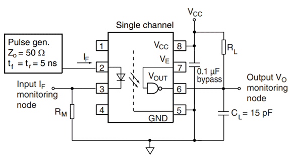
The Capacitor 0.1uF is a bypass capacitor across the Supply rail. The input signal should has an impedance of minimum 50 ohms with rise time and falls of 5nS of greater for the IC to respond. The input signal can be probed (if required) on pin 3 and the pull down resistor Rm is optional and can be used only if you are connecting the signal to scope.
As told earlier the output (pin 6) is an open drain transistor and hence it can either sink current or remain floating. So to avoid floating we should use a pull up resistor RL, the value of RL can be between 330 ohm to 4K depending upon the load connected.
The pin 7 is the Enable pin, this pin has an in-built pull up resistor hence by default the IC is enabled when powered. When connected to ground it will disable the output. The pin can be put into use to create strobe circuits etc.. The below truth table will help you understand the working of Enable pin.
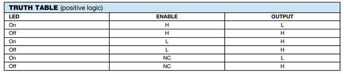
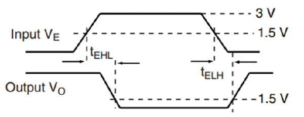
Since the output is of open drain type, note that when the input is high the output will be low and vice versa. Since the IC is commonly used for fast switching another thing to consider is the propagation delay. When the input is logic on the output turn off only after 48ns (TELH) and when the input is logic off the output turns on only after 50ns (TEHL). The same can be understood with the below switching diagram.
Applications
- Camera Strode lights
- High speed ADC and DAC
- Fibre/optic communication
- Noise isolation circuits
- Input / Output isolation circuits
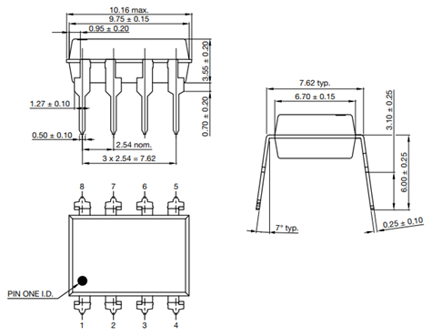
2D-Model and Dimensions