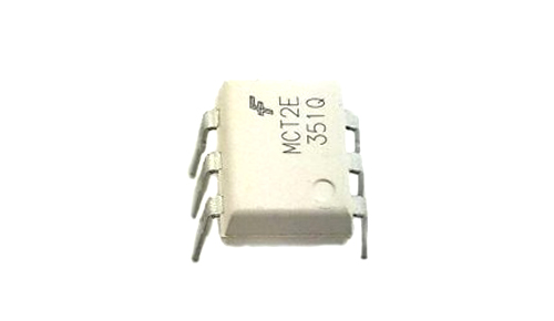
MCT2E - Phototransistor Optocoupler IC
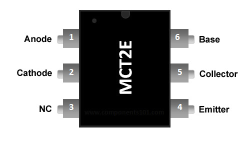
MCT2E Pin Configuration
|
Pin Number |
Pin Name |
Description |
|
1 |
Anode (A) |
Anode pin of the IR LED. Connected to logic input |
|
2 |
Cathode (C) |
Cathode pin of the IR LED |
|
3 |
NC |
Cannot be used |
|
4 |
Emitter (E) |
Emitter pin of the Transistor. Connected to isolated ground. |
|
5 |
Collector (C) |
Collector pin of the Transistor. This is the logic output pin |
|
6 |
Base (B) |
Base pin of the Transistor. It is normally not used for transistor mode, but will be used in diode mode |
MCT2E Features and Specifications
- Input Diode Forward Voltage: 1.25V
- Collector-Emitter Voltage: 30V
- On-State Collector Current: 5mA
- Transistor HFE: 300
- Rise Time: 5us
- Fall Time: 5us
- Available as 6-pin PDIP with and without M-suffix
Note: More details can be found at the MCT2E datasheet which is available for download at the end of this page.
MCT2E Equivalents
4N35 Optocoupler IC
Alternatives Opto-couplers
MOC3021 (Zero Cross TRIAC) , MOC3041 (Non-Zero Cross TRIAC), FOD3180 (High-Speed MOSFET),
Where to use MCT2E Phototransistor Optocoupler
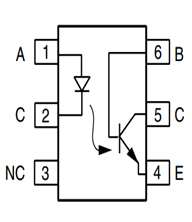
MCT2E is a phototransistor Optocoupler, as the name “phototransistor” suggests it has a transistor which is controlled based on light (photon). So this IC basically has an IR (infrared) LED and a photo-transistor inside it. When the IR led is powered the light from it falls on the transistor and it conducts. The arrangement and pin-outs of the IR LED and the photo-transistor is shown below.
This IC is used to provide electrical isolation between two circuits, one part of the circuit is connected to the IR LED and the other to Photo-transistor. The digital signal given to the IR LED will be reflected on the transistor but there will be no hard electrical connection between the two. This comes in very handy when you are trying to isolate a noisy signal from your digital electronics, so if you are looking for an IC to provide optical isolation in your circuit design, then this IC might be the right choice for you.
How to use MCT2E
The MCT2E can be used in two modes, the Phototransistor mode and the photodiode mode. Out of which the Phototransistor mode is mostly used, so let us look at that mode first.
In the Photo-transistor mode we will not be using the base pin (pin 6) of the transistor; we just have to connect the anode pin of the IR LED (pin 1) to the logic input which has to be isolated and the cathode (pin 2) of the IR led to the ground. Then Pull high the collector pin of the transistor using a resistor (here I have used 1K) and connect the collector pin to the output of your desired logic circuit. The Emitter (pin 4) is grounded.
Note: The ground line of the IR LED (pin 2) and the ground line of the transistor (pin 4) will not be connected together. This is where the isolation occurs.
Now, when the Logic input is low, the IR LED will not conduct and hence the transistor will also be in off state. Hence the Logic output will remain high, this high voltage can be set anywhere up-to 30V (Collector-Emitter Voltage) here I have used +5V. There pull-up resistor 1K acts as a load resistor.
But when the Logic input is made high, this high voltage should be a minimum of 1.25V (Diode Forward voltage) the IR LED conducts and so the photo-transistor is also turned on. This will short the collector and emitter and hence the Logic Output voltage will become zero. This way the logic input will be reflected at the logic output and still provides and isolation between the two. The complete working can also be understood form the GIF file above.
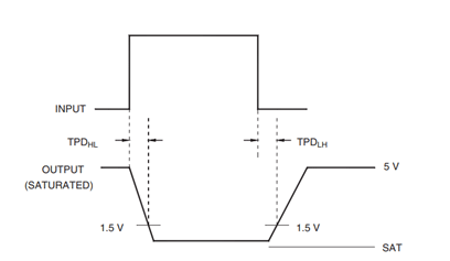
Another important parameter to consider while using an Optocoupler, is the rise time (tr) and fall time (tf). The output will not get high as soon as the input logic is made low and vice versa. The below waveform shows the time taken for the output to transit from one state to another. For MCT2E, the rise time (TPDHL) and fall time (TPDLH) is 5us.
Applications
- Electrical Isolation circuits
- Microcontroller I/O switching circuits
- Signal isolation
- Noise coupling circuits
- Isolation digital from analog circuits
- Ac/DC Power control
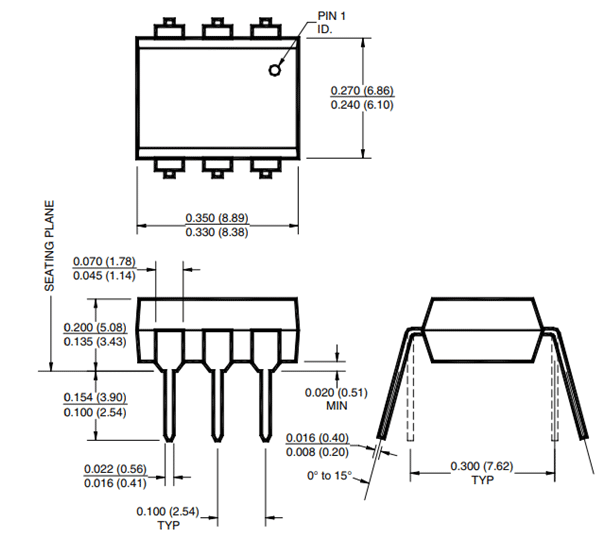
2D-Model and Dimensions


MOC3021 (Zero Cross TRIAC) ,…
MOC3021 (Zero Cross TRIAC) , MOC3041 (Non-Zero Cross TRIAC)
datasheet say both are with zero-crossing