Arduino UNO Q bridges high-performance computing with real-time control.
Decoupling Capacitors and Bypass Capacitors – Working, Applications and Differences
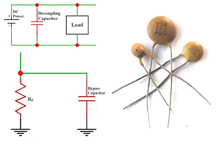
Capacitors are one of the most used passive components. From simple amplifier circuits to complex filter circuits you can find them being used in many analog and power electronic circuits. While we have already learnt the basics of a capacitor and how it works there are a wide variety of applications for capacitors. The Bypass capacitors and the Decoupling capacitor are such two application terms that are widely used when referring to a capacitor in a circuit. In this article we will learn about these two capacitors types, how they function in a design and how to select a capacitor that is to be used as a bypass capacitor or decoupling capacitor.
While the terms Bypass capacitors and Decoupling capacitor are used interchangeably, they have their own differences. When powering any device the prime goal will be to provide very low impedance (Relative to ground) for the input power. In order to achieve this condition bypassing is introduced to circuits. To understand the difference between the two types of capacitors, let’s dive into them deeply.
Decoupling capacitor
Decoupling capacitors are used for Isolating or decoupling two different circuits or a local circuit from an external circuit, in other words the decoupling capacitor is used for decoupling AC signals from DC signals or vice versa.
The real fact is the decoupling capacitor is used for both the purpose and we can define the Decoupling capacitors as the capacitor that are used for removing the power distortion and noise and protect the system/IC by providing pure DC supply.
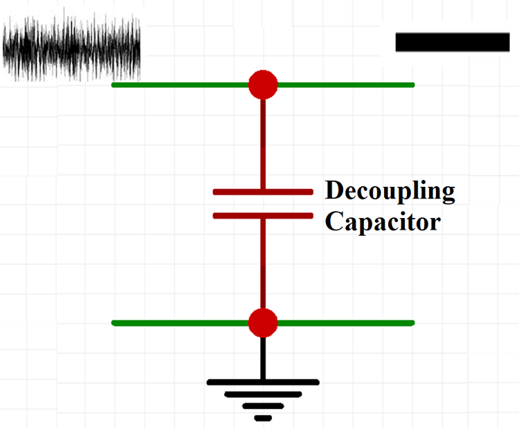
The Decoupling process is really important when it comes to logic circuits. For example, consider a logic gate that can operate at a supply voltage of 5V, if the Voltage goes above 2.5V it will read as High signal and if the Voltage goes below 2.5V it will read as Low signal. So, if there is a noise in the supply voltage it will trigger highs and lows in the logic circuit, hence the DC Coupling capacitors are widely used for logic circuits
Positioning a Decoupling Capacitor
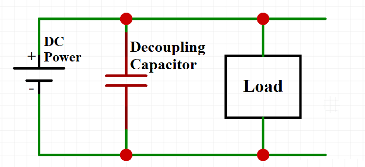
The decoupling capacitor should be placed between the power supply and the load/IC in parallel to one another. When the DC Power supply is delivering the power to the circuit the decoupling capacitor will have infinite reactance on DC signals and they will not have any effects on them, but it has much less reactance on AC signals so they can pass through the decoupling capacitor and they will be shunted to the ground If required. The capacitor will create a low impedance path for the high frequency signals to get shunted resulting in a clean DC signal.
The positioning involves two different capacitors, consider a capacitor of capacitance 10µF placed away from the IC which is used to smooth out the low frequency changes in the power supply and a 0.1 µF capacitor kept closer to the IC which is used to smooth the high frequency changes in the power supply.
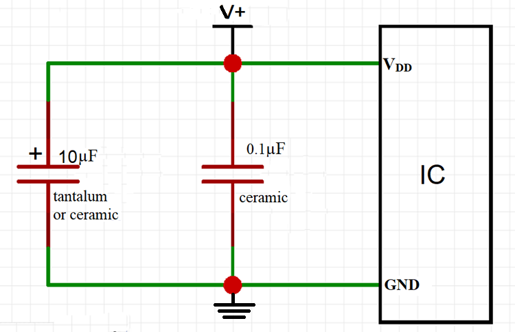
The most used type of capacitors for low frequency smoothing is the electrolytic capacitors and the capacitors used for high frequency smoothing are the surface mount ceramic capacitors.
Value of the Decoupling Capacitor
Unlike Bypass capacitors there are not much riles to choose the value of a decoupling capacitor. As the decoupling capacitors are used widely there are certain standards for choosing the value.
- The Low frequency noise decoupling capacitor value should be typically between 1 µF to 100 µF
- The high frequency noise decoupling capacitor should typically value between 0.01 µF to 0.1 µF.
The exact value of the capacitors to be used is always provided with the ICs data sheet. The decoupling capacitors should always be connected directly to a low impedance ground plane for its effective operation.
Bypass Capacitor
The Bypass capacitor is used to prevent noise from entering the system by bypassing it to the ground. The bypass capacitor is placed between the pins of supply voltage (Vcc) and Ground (GND) in order to reduce both Power supply noise and the result of spikes on the supply lines. For different devices and different components the capacitor has the ability to suppress both inter and intra system noises.
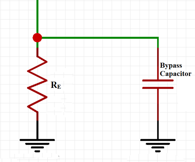
In operation the capacitor shorts any kind of AC signal to the ground so that the AC noise in a DC signal is removed resulting in a cleaner and pure DC signal. For example, let’s look into the Emitter and Cathode Bypass capacitors.
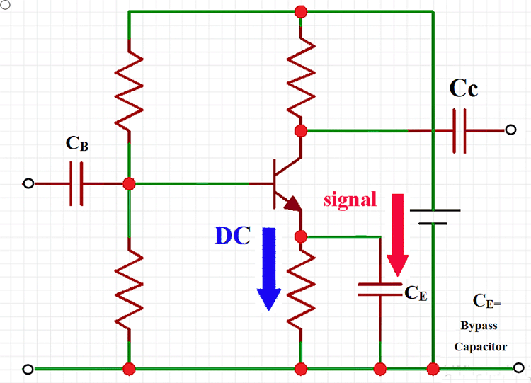
Emitter Bypass Capacitor
Consider Common Emitter (CE) amplifier with an emitter resistance, if a bypass capacitor is connected parallel with an emitter resistance the voltage gain of the CE amplifier increases and if the capacitor is removed extreme degeneration is developed in the amplifier circuit and voltage gain will be reduced.
Cathode Bypass Capacitor
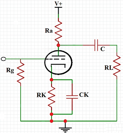
When a capacitor is connected across the cathode resistance and if the capacitor is large enough, it will act as a short circuit for audio frequency and eliminates the negative feedback. It also acts as an open circuit for a DC and maintains the DC grid bias.
How to select the value for a Bypass Capacitor
The reactance of the capacitor added to the circuit should be 1/10th or less of the resistance in parallel. We all know that the current always take the low resistance path, if you want to shunt the AC signal to the ground the capacitor should have a lower resistance. The capacitance value of the bypass capacitor to be used can be calculated using the formula
C = 1/2πfXC
With the above bypass capacitor formulae, let’s consider you need to find the capacitance of the capacitor connected across the resistor of resistance 440Ω, we know the reactance is always 1/10th of the resistance, hence the reactance will be 44Ω and the standard frequency of the Indian electrical network is 50Hz, so the bypass capacitor value can be calculated as
C = 1/2(3.14)(50)(44)
The capacitance of the capacitor across the 440 Ω resistor should be 73µF. Using the same you can find out the value of capacitors that can be used in a circuit.
Applications of Bypass Capacitor
The bypass capacitors are almost used in all the analog and digital circuits for removing unwanted signal from the supply voltage, some of the notable applications where they are used
- They are used between amplifier and loudspeaker for a clear audio.
- Used in DC/DC converter
- Used in signal coupling and Decoupling
- Used in High Pass(HP) Filter and Low Pass (LP) Filters
Difference between Bypass and Decoupling Capacitor
When you look at the purpose they are used for, there is not much difference between the two types of capacitors. Surprisingly, most of the times the decoupling capacitors are also called as the Bypass capacitors. This is because they are shunted to the ground sometimes.
Some of the few noticeable difference between the bypass capacitor and decoupling capacitors are , the bypass capacitor is designed to shunt the noise signals where as the decoupling capacitors are designed to smoothen the signal by stabilizing the distorted signal. For shunting the signal we can just use a single electrolytic capacitor but for soothing the signal we will need two different types of capacitor.


