


Optimized with highly sensitive cap touch sensors, extensive peripheral circuits and 125℃ operation
Introduction to Diodes: Basics, Types, Characteristics, Applications & Packages
While the Resistors, Capacitors and Inductors form the basic elements of a circuit, it is the semi-conductor device that actually holds the magic within. Every electronic circuit has dozens of semi-conductor device like Diodes, Transistors, Regulators, Op-Amps, Power switches etc. inside them. Each of them has their own properties and application. In this article let’s cover the most basic semi-conductor device, the diodes.
Perhaps, you might have already heard the ramble that “Diodes are semi-conductor devices with two terminals that conduct only in one particular direction allowing current to pass through them…” but why is that? And what does it actually has to do with us while designing a circuit? What are the different types of diodes and in which application should we use them? Hold tight for you will be answered to all these questions as you read down this article.
What is a Diode?
Let’s start by answering the most basic question. What is a Diode?
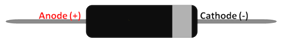
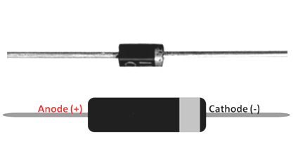
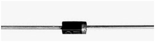
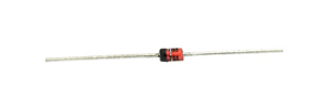
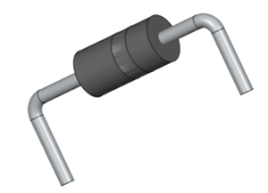
A Diode, as I told earlier is a semi-conductor cylindrical component with two terminals. There are many types of diodes but the most commonly used one is shown below.
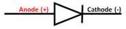
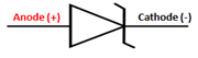
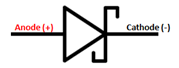
The two terminals are named as Anode and Cathode, we will get into the symbol and how to identify the terminals later, but for now just remember that any diode will have only two terminals (at least most of them) and they are Anode and Cathode. Another golden rule with diodes is that they allow current to pass through them in only one direction that is from Anode to Cathode. This property of diode is what makes it useful in many applications.
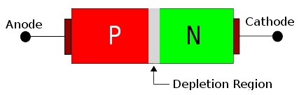
To know why they conduct in only one direction we have to look at how they are constructed. A Diode is made by joining two equally doped P-type semi-conductor and N-type semi-conductor material. When these two materials are joined together something interesting happens, they form another small layer in-between them called the depletion layer. This is because the P-type layer has excess hole and the N-type layer has excess electrons and they both try to diffuse into each other forming a high resistance blockage between both the materials like in the image shown below. This blockage layer is called as depletion layer.
This depletion layer (Blockage) has to be broken if the current has to flow through a diode. When a positive voltage is applied to the Anode and a Negative voltage is applied to the Cathode the diode is said to be in forward biased condition. During this state the positive voltage will pump more holes into the P-type region and the negative voltage will pump more electrons into the N-type region which causes the depletion layer to breakdown casing the current to flow from Anode to Cathode. This minimum voltage required to make the diode conduct in forward direction is called the forward breakdown voltage.
Alternatively, if a negative voltage is applied to Anode and positive voltage is applied to Cathode the diode is said to be in reverse biased condition. During this state the negative voltage will pump in more electrons to P-type and N-type material will get more holes from positive voltage which makes the depletion layer even stronger and thus allowing no current to flow through it. Keep in mind that these characteristics are applicable only to an ideal diode (theoretical) practically there will be a little bit of current flowing even in reverse biased mode. We will discuss this later.
The above animation illustrates the working of diode in a circuit, there are two circuits both in which we are trying to glow a Led with a battery. In one circuit the diode is forward biased and in the other the diode is reverse biased. When the simulation in run, you can notice that only the forward biased Diode allows current to flow though it thus glowing the LED the reverse biased diode does not allow any current to pass through it.
Diode Types, Pinouts and symbols
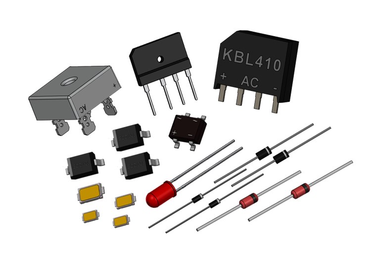
Now, that we have understood the basics of diode it is important to know there are different types of diodes each having a special property and application. In this article let’s cover only the three main types of diodes they are the Rectifier Diode, Zener Diode and Schottky Diode. The picture, terminal and symbol of all diodes are tabulated below
|
Diode Type |
Pinouts |
Symbol |
|
Rectifier Diode |
|
|
|
Zener Diode |
|
|
|
Schottky Diode |
|
|
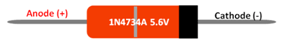
As shown in the table the Rectifier Diode and Schottky Diode looks similar in appearance, but the Schottky diode is usually bigger in size than the conventional diodes. The Zener diode on the other hand can be easy identified with its peculiar orange colour and grey line on it, as shown in the table above.
The anode and the cathode terminals can be identified with the grey line on the diode, the pin near to the grey line will be cathode. Similarly with symbols the bottom of the triangle will always be the Anode and the other will be Cathode. It is very important to remember this since it always considered being self understood while interpreting a circuit of diode connection.
Diode Terminologies and Characteristics
When you are selecting a diode for your circuit or trying to understand the operation of a diode in a circuit you have to consider the specifications of the diode which can be found in its datasheet. In order to understand what the values actually mean let us look into few commonly used terminologies.
Forward Voltage Drop (Vf): When a diode is working in forward biased condition, it will allow current to flow through them. During this state there will be some voltage drop across the diode this voltage drop is called as the forward Voltage drop. For an ideal diode it should be as low as possible.
Maximum Forward Current (If): We already know that diode will allow current to flow through it when it is in forward biased, what is the maximum current that can be allowed is answered by the Maximum forward current. Normally it should be ensured that this current is more than the load current of your circuit.
Reverse break down current (Vr): Okay, here is a catch I told you that a diode will not allow current to flow through it when it is reverse biased. It holds true but not for all values voltage. So the maximum voltage upto which the diode can withstand breakdown is called as Reverse breakdown voltage. Normally the values of such voltage will be very high, for example if the reverse breakdown voltage is 500V the diode will not allow current to pass through it in reverse biased state until the voltage exceed this 500V.
Reverse Biased Current (Ir): While it is true that the diode will not allow current to flow though it in reverse biased mode the value of current will not be ideally zero. There will be a very small and negligible (depends on the circuit) current still flowing though the diode. This current is called the Reverse Biased current. The value of this current will be in range of mA or even in uA. For an ideal Diode the value of this current should be as low as possible. The current is called as the reverse leakage current.
Reverse Recovery Time: Say you are operating you diode in forward biased mode and then change it to reverse biased mode by changing the polarity of the voltage. Now the diode will not come to a sudden halt, it will require some time to block the flow of current through it. This time is called as the Reverse Recovery time.
Terminal (I-V) Characteristics of a Junction Diode: There are still other parameters like the Power dissipation, Thermal Resistance etc. associated with a diode. These values can also be found in the datasheet of the diode. To know more about diode let us look at on important graph of a diode which is the Current vs Voltage I-V Curve. The I-V curve of an ideal diode will look something like this.
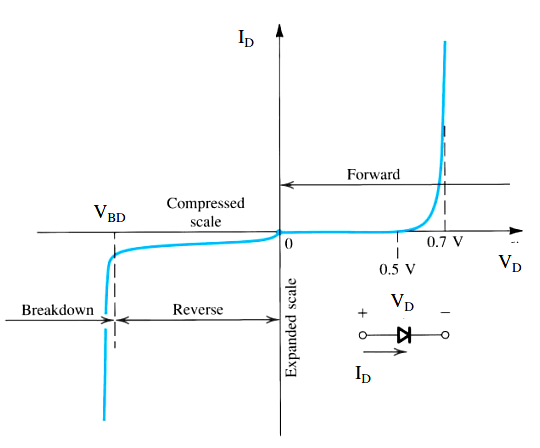
Here in the first quadrant you can see the diode operating in the Forward Biased mode and in the third quadrant the diode is operating in the Reverse biased and Break down Region. The X-axis of the graph indicates the voltage across the diode and the Y-axis indicates the current though the Diode. During the forward biased mode you can notice that the diode starts to conduct (allow current) only when the voltage across the diode (VD) is greater than 0.5V, this is the value of forward voltage of the Diode for a silicon diode this forward voltage can be upto 0.7V as shown in the graph above.
During the Reverse biased the voltage across the diode is in negative potential so the current is also shown in negative direction. Here as you can see the diode does not allow current (expect for a small value) to flow across it until the breakdown voltage (VBD) is reached.
Application Circuits
Diodes have a wide range of application based on their property and type. Lets us try to cover the most important applications of the Rectifier, Zener and Schottky Diode with their circuit Diagrams.
Rectifier Diode
The Rectifier Diode a.k.a Common Diode is the most commonly spotted diode in any power supply circuit be it a simple Linear Power supply or an SMPS circuit . As the name suggests these diodes are used for Rectification purpose in circuits like Full wave and Half wave rectifier. Apart from that they are also used as Freewheeling diodes in switching applications and converter circuits.
Rectifier Circuit
The Rectifier Diodes are used both in Half wave and Full Wave rectifier diodes. Let us look at the Half wave rectifier circuit for the sake of simplicity. The circuit diagram and the graph for a half wave rectifier is shown below
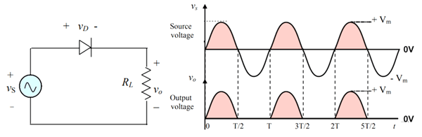
The Input Voltage source Vs is an AC sinusoidal wave with RMS voltage of 220V. This AC wave can be rectified with a help of a single diode. As shown in the graph during the Positive half cycle the diode is forward biased and hence the Output voltage is present across the load and the current flows in the positive direction. But during the negative half cycle the diode is reverse biased and hence no current reaches the load and output voltage stays at 0V as shown in the graph above. This way the current is always allowed to flow only in one direction and thus converting the AC to DC.
Of course, this circuit has a lot of drawbacks like the output voltage is not uniform and is not used practically. But now that you have got the idea you can look into full bridge rectifiers that have four diodes and are commonly used in linear regulator circuits. Also A rectifier circuit will have a capacitor at the end of it to filter the ripples if you want to know more on capacitor read the introduction to capacitor article.
Zener Diode
The Zener Diode is widely used in two circuits one is as a crude voltage regulator and the other is a over voltage protection circuit. The Zener diode has two important rating to look for which is the Zener voltage and Power. The common available values of diodes are 3.9V, 4.7V, 5.1V, 6.8V, 7.5V and 15V
In the below circuit the input voltage can vary between 0V to 12V but the output voltage will never exceed 5.1V since the Reverse breakdown voltage (Zener Voltage) of the Zener is 5.1V. When the Input voltage is less than 5.1V the Output voltage will be equal to the input voltage, but when it exceed the 5.1V the output voltage will be regulated to 5.1V.
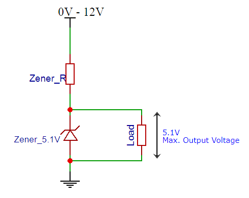
This property of the circuit can be used for protecting ADC pins (Over voltage protection circuit) which are 5V since the pin can read voltage form 0-5V but if it exceeds 5V the Zener will not allow the excess voltage. Similarly the same circuit can be used to regulate 5.1V for a load when the input voltage is high. But the current limitation is very less for such a circuit.
While designing circuit with Zener one important thing to consider is the Zener resistor. This resistor is used to limit the current through Zener thus protecting it from heating up and getting damaged. The value of a Zener resistor depends on the Zener voltage and Power rating of the Zener diode. The formula to calculate the Zener series resistor Rs is shown below
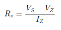
For a 1N4734A Zener diode the value of Vz is 5.9 V and Pz is 500mW, now with supply voltage (Vs) of 12V the value of Rs will be
Rs = (12-5.9)/Iz
Iz = Pz/Vz = 500mW / 5.9V = ~85mA
Therefore, Rs = (12-5.9)/85 = 71 ohms
Rs = 71ohms (approx)
Schottky Diode
Schottky Diode is also used in protection circuits like the Reverse Polarity Protection circuit, because of its low forward voltage drop. Let us take a look at a common reverse polarity protection circuit
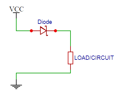
When the Vcc and Ground is connected in the right polarity the diode conducts in forward direction and the LOAD receives the power. The advantage here is that the Forward voltage drop across the diode is very less say around 0.04V compared to the 0.7V of a rectifier diode. This way there will be not much power loss across the Diode, also Schottky diode can allow more current to pass though it then a common diode and it also has faster switching speed hence can be used in high frequency circuit. Now that I have said this you might get a question.
What is the difference between Schottky diode and Common Diode?
Well, yes the Schottky diode has faster switching speed, low conduction loss and higher forward current than a Common Diode. It might sound superior to a common diode but it has one major drawback. That is it has low Reverse breakdown voltage, because of this feature it cannot be used in Rectifier circuits since rectifier circuits will always have high reverse voltage appearing across it during switching.
Special Diodes
Apart from the commonly used Rectifier, Zener and Schottky types of Diodes there are other special diodes which has specific application lets quickly run through them.
LED: Yes, the Light Emitting Diode(LED) as the name states is a diode. You should be already familiar with these things as they are commonly found and used. Again there are many types in LED, but the 5mm Round LED is the most commonly spotted one.
Bridge Rectifier: As we know the rectifier diode is used in rectifier circuit and for a full bridge rectifier circuit we will need four diodes connected in an orderly fashion. This set-up itself is available in a package called rectifier diode. The RB156 is one such example.
Photodiode: The Photodiode is a diode which allows current to pass though it based on the light falling on it. It is used as a sensor for detecting light, it can be commonly found in Line follower, obstacle avoider robots and even as a object counter or speed sensor device. You can know more about photodiode in this link.
Laser diode: The Laser light is also a type of a Diode similar to a LED. They have the similar property of a diode but during forward biased mode they emit light with a voltage drop across them acting as a load. The 650nM Laser Diode is the most commonly available laser diode.
TVS Diode: Another important special type of diode is the TVS diode, which stands for Transient Voltage suppresser. It is a special type of diode which is commonly used in power supply circuits to deal with Voltage spikes in order to protect the circuit. These diodes are also called as transil diode or thyrectors.
Varactor Diodes: Varactor Diodes are used as variable capacitors. When this diode is operated in Reverse biased mode the width of the depletion region can be controlled which makes it act as a capacitor. These diodes are also called as Varicap Diode and are commonly used in RF circuits.
Different Types of Diodes Packages
Now that we have learnt all the basics of Diodes, I believe you can now select a diode as required for your circuit. But do far we have seen one through-hole type diodes which is commonly available and good and for prototypes, but in most products you will not find these though hole packages. There are many different types of Diode packages which we will discuss now.
Through Hole Package
These are the commonly used one which are breadboard and Perf board friendly. These packages are named as DO-7,DO-35, DO-41, DO-204 etc out of which the DO-41 is most common. These Packages are also called as Axial Lead Diodes.
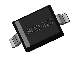
Surface Mount Styles
In most final products which are ready for production uses SMD components. These are cheaper than though hole and has a small form factor. SOD-323, SOD-523, SOD-123 SOD-80C are some of the popular diode SMD packages. In most power circuit designers still use through hole type since they have high current capacity and less EMI problems so SMD is normally preferred in digital circuits.
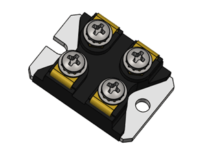
3-Terminal Bolt Mount
There also exist some three terminal special diodes which are used in advanced applications like space industry. They have high current and switching capability. These can be found in TO-64, TO-208, TO-254 packages. The can a slot in between allowing them to be bolted to a head sink body, these are also called as Bolt mount diodes.