MP6550 Bi-directional DC Motor Driver
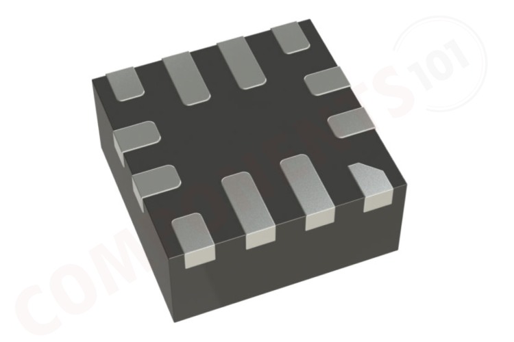
The MP6550 is a H bridge motor driver from Monolithic Power Systems (MPS). The H bridge consists of 4 N channel Mosfets and the IC feature integrated charge pump for the high side Mosfet drivers. This IC can be used for bidirectional control of one brushed DC motor. It offers a wide operating voltage range of 1.8 V to 22 V and can deliver a continuous current of up to 2A. The MP6550 has built-in current sensing and current limiting as well as protection against under-voltage, over-current, and over-temperature conditions. The MP6550 has a PWM input interface, which is compatible with industry-standard devices. The MP6550 requires a minimal number of readily available, standard external components, and is available in a QFN-12 (2mmx2mm) package.
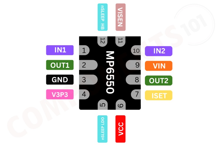
MP6550 Pinout Configuration
Here are the pinout details for MP6550.
| Pin no | Name | Description |
| 1 | IN1 | Input1. |
| 2 | OUT1 | Switch output 1. |
| 3 | GND | Ground. |
| 4 | V3P3 | 3.3V regulator output. |
| 5 | nSLEEP_LDO | Sleepmode input of LDOoutput. |
| 6 | VCC | Internalcircuitrysupply bypass. |
| 7 | ISET | Current programming resistor. |
| 8 | OUT2 | Switch output 2. |
| 9 | VIN | Supply voltage. |
| 10 | IN2 | Input 2. |
| 11 | VISEN | Current-sense output voltage. |
| 12 | nSLEEP_HB | Sleepmode input of H-bridge. |
Features of MP6550
MP6550 bi-directional DC motor Driver has the following key features:
- Wide 1.8V to 22V Operating Input Range
- 2A Continuous Driver Current
- MOSFET On Resistance (HS + LS) 240mΩ
- Cycle-by-Cycle Current Regulation/Limit
- Built-In 3.3V Reference Output
- PWM Input Interface, Compatible with
- Industry-Standard Devices, Up to 100kHz Low Standby Circuit Current
- Thermal Shutdown
- Internal Charge Pump
- Cycle-by-Cycle Over-Current Protection
- Short-Circuit Protection
- Available in a QFN-12 (2mmx2mm) Package
Manufacturers of MP6550:
The MP6550 is manufactured by Monolithic Power Systems. There are no alternative manufacturers for the same part number as of the date of writing this article.
MP6550 Equivalents
There are no pin-to-pin compatible equivalents for MP6550 that we could find
MP6550 Alternatives
If you are looking for an alternative for MP6550 you can look at the other ICs from these.
L293D, L298, TB6612FNG, DRV8833, MAX1508, DRV8837, MAX1919, L9110, TA6586, A3908, MP6513
Note: Complete technical details can be found in the MP6550 datasheet at this page’s end.
MP6550 Schematics
The following image shows the typical circuit diagram for MP6550.
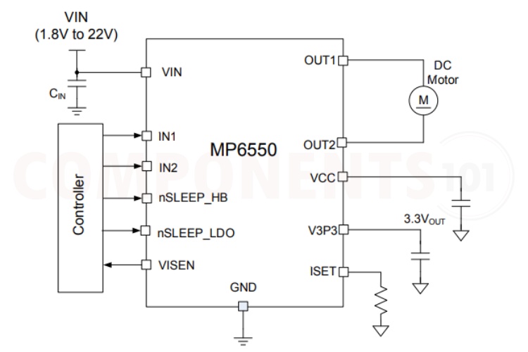
In this circuit VIN is the input voltage supply to the MP6550. The voltage can range from 1.8V to 22V, which is supplied to the VIN pin of the IC. CIN is a decoupling capacitor connected between VIN and GND to filter out any noise from the power supply.IN1 and IN2 are the control inputs from the external controller, which determine the direction and operation of the motor. nSLEEP_HB and nSLEEP_LDOare the sleep mode control pins, which can be used to put the H-Bridge or the LDO into sleep mode to save power.VISEN pin is used for current sensing. OUT1 and OUT2 are the output pins that connect to the DC motor. The motor will rotate based on the control signals received on IN1 and IN2. VCC This is the logic supply voltage for the IC. V3P3 pin outputs 3.3V, which is typically used to power other parts of the circuit or the controller. SET pin is used to set the current limit for the motor driver. A resistor is connected between ISET and GND to set this limit.
| IN1 | IN2 | OUT1 | OUT2 | Function (DCMotor) |
| L | L | Z | Z | Coast |
| L | H | L | H | Reverse |
| H | L | H | L | Forward |
| H | H | L | L | Brake |
Having Trouble with MP6550?
How to do MP6550 Arduino Interfacing?
For controlling the MP6550 you will need five GPIO pins. Connect the inputs and sleep mode pins of MP6550 to gpio pins of Arduino, set them as output and by changing the state of these pins you can control the MP6550, and the motor connected to it. Also connect the current sense pin Arduino and set it as input pin. If you don’t need low power sleep mode and current sensing you can ignore those pins. Then using the two control pins you can control the direction of motor. To achieve speed control, you can use PWM.
Why does motor is not running even after signal to the IN1 and IN2 control pins?
Make sure the motor driver is no inm sleep mode. Both nSleep_HB and nSleep_LDO should be in high state.
How to minimize the jerking of motors?
Add .1uf capacitor parallel with motor connections to minimize jerking.
Is a heat sink necessary for the working of MP6550?
No. For most applications, the MP6550 can operate without a heat sink within its specified operating conditions.
Applications of MP6550
- Portable printers/scanners
- Camera lens/shutter control
- Battery powered toys and games
- Consumer Products
- Medical Devices
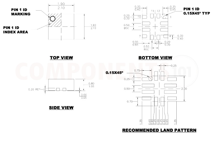
2D Model and Dimensions of MP6550
Here you can find the mechanical drawings of MP6550 along with its dimensions. The dimensions can be used to create custom footprints of the chip and be used for PCB or CAD modeling.