RT8059 – 1.5MHz, 1A, High Efficiency Step-Down DC/DC Converter
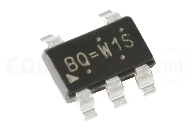
The RT8059 is a low-cost high-efficiency PWM step-down DC/DC converter. This small IC delivers up to 1A output current. It has a wide input voltage range from 2.8V to 5.5V, making it suitable for a variety of power sources. The RT8059 comes with soft-start, lower internal reference voltage with 2% accuracy, over-temperature protection, and over-current protection. It has an Internal synchronous rectifier with low RDS(ON) which reduces conduction loss at PWM mode. The RT8059 doesn’t require any external Schottky diode. The RT8059 has different modes, which helps to achieve maximum efficiency. The RT8059 can be shifted into shutdown mode by pulling the EN pin to low. In shutdown mode, the IC consumes less than 0.1μA. This small IC is available in the TSOT-23-5 package, which is ideal for small PCB area applications.
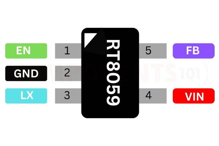
RT8059 Pinout Configuration
Here are the pinout details for RT8059.
| Pin No. | Pin Name | Pin Function |
| 1 | EN | Chip Enable (Active High). Do not leave the EN pin floating. |
| 2 | GND | Ground. |
| 3 | LX | Switch Node. |
| 4 | VIN | Power Input. |
| 5 | FB | Feedback Input Pin. |
Features of RT8059
RT8059 Switching regulator has the following key features:
- Wide Input Voltage from 2.8V to 5.5V
- Adjustable Output from 0.6V to VIN
- 1A Output Current with up to 95% Efficiency
- No Schottky Diode Required
- 1.5MHz Fixed Frequency PWM Operation
- Small TSOT-23-5 Package
- RoHS Compliant and Halogen Free
Manufacturers of RT8059:
The RT8059 is manufactured by Richtek. There are no alternative manufacturers for the same part number as of the date of writing this article.
RT8059 Equivalents
If you are looking for an equivalent replacement for RT8059, you may consider using TLV62565 or TLV62566.
RT8059 Alternatives
If you are looking for an alternative for RT8059 you can look at the other IC from these.
LM2596, XL6009, MC34063, MP9486, MP1584, TPS54231, LM2576, CS1411, LT1070, TPS5430, NCP3170, LT1765, LT1370
Note: Complete technical details can be found in the RT8059 datasheet at this page’s end.
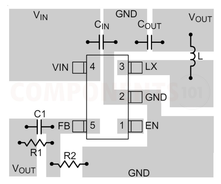
RT8059 Circuit Diagram
The following image shows a simple circuit diagram for RT8059.
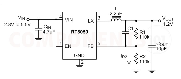
This is a typical high-efficiency step-down DC-DC converter application circuit for using RT8059. This circuit is used to convert the input voltage of 2.8-5.5v to 1.2V.
The input supply is connected to pin 4 (VIN) of the RT8059. CIN is a 4.7µF capacitor connected between the VIN pin and the ground. This capacitor stabilizes the input voltage and reduces voltage spikes. Pin 1 (EN) is the enable pin, which controls whether the converter is on or off. If this pin is pulled high, the converter is enabled. If pulled low, the converter is disabled. Here we have pulled the pin to high. Pin 3 (LX) is the switch node where the inductor (L) is connected. The LX pin switches between VIN and ground to regulate the output voltage. The inductor stores energy when the LX pin is connected to VIN and releases energy to the output when the LX is connected to the ground. 10µF capacitor connected between VOUT and ground. It smooths out the output voltage and reduces ripple. The output voltage is divided by resistors R1 and R2 and fed back to the FB pin to regulate the output voltage. R1 and R2 form a voltage divider network. The values of R1 and R2 set the output voltage. In this case, both R1 and R2 are 110kΩ, which sets the output voltage to 1.2V based on the feedback reference voltage of 0.6V.
RT8059 Troubleshooting Guide
The RT8059 is not providing the desired output voltage?
You have to check the inductor value as well as the voltage divider network. Make sure the values of resistors are correct.
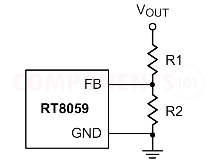
For adjustable voltage mode, the output voltage is set by an external resistive voltage divider according to the following equation :
VOUT = VREF(1+ R1/R2)
where VREF is the internal reference voltage (0.6V type.)
My RT8059 is not providing any output. What could be the issue?
First, ensure that the power supply voltage and current are sufficient. Check the connections to the RT8059. Properly connect the inductor.
There is a lot of ripples in the output?
Check the enable pin it must be I high state to get the output. Normally it is tied to the Vin.
Things to Consider When Using RT8059 in your Design:
When designing with the RT8059, here are some important considerations and design tips to keep in mind:
Thermal Considerations
For continuous operation, do not exceed the absolute maximum junction temperature. The maximum power dissipation depends on the thermal resistance of the IC package, PCB layout, rate of surrounding airflow, and the difference between junction and ambient temperature. The maximum power dissipation can be calculated by the following formula: PD(MAX) = (TJ(MAX) − TA) / θJA where TJ(MAX) is the maximum junction temperature, TA is the ambient temperature, and θJAis the junction to ambient thermal resistance. For recommended operating condition specifications of the RT8059, the maximum junction temperature is 125°C and TA is the ambient temperature. The junction to ambient thermal resistance, θJA, is layout dependent. For TSOT23-5 packages, the thermal resistance, θJA, is 255°C/W on a standard JEDEC 51-3 single-layer thermal test board. The maximum power dissipation at TA = 25°C can be calculated by the following formula: PD(MAX) = (125°C − 25°C) / (255°C/W) = 0.392W for TSOT-23-5 package.
Layout Considerations
Follow the PCB layout guidelines for optimal performance of the RT8059. Keep the trace of the main current paths as short and wide as possible. Place the input capacitor as close as possible to the device pins (VIN and GND). LX node experiences high-frequency voltage swings and should be kept in a small area. Keep analog components away from the LX node to prevent stray capacitive noise pick-up. Place the feedback components as close as possible to the FB pin. GND and Exposed Pad must be connected to a strong ground plane for heat sinking and noise protection.
Applications of RT8059
- Network Interface Crads
- Cellular Telephones
- Portable Appliances
- Wireless and DSL Modems
- MP3 Players and Portable Instruments
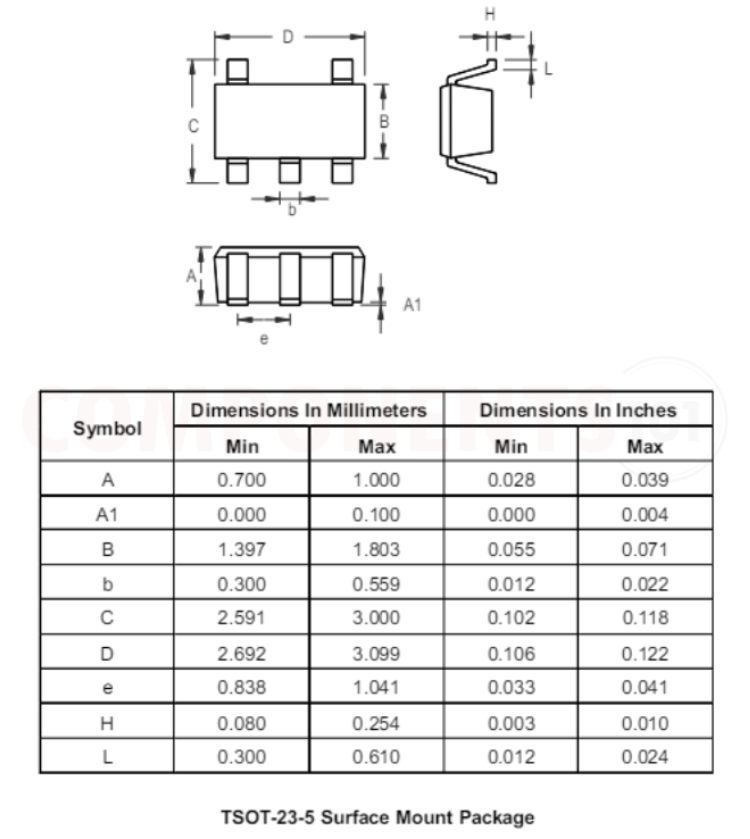
2D Model and Dimensions of RT8059
Here you can find the mechanical drawings of RT8059 along with its dimensions. The dimensions can be used to create custom footprints of the IC and be used for PCB or CAD modelling.