XL6009 PWM Switching Regulator (Buck-Boost)
The XL6009 is a Buck-Boost switching Regulator, meaning it takes in an Input Voltage and then switches it to produce a regulated output voltage which could be greater or lesser than the Input Voltage.
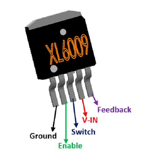
Pin Configuration
|
Pin Number |
Pin Name |
Description |
|
1 |
Ground |
Connect to system Ground |
|
2 |
Enable Pin |
Make pin High to turn on device and Low to turn off device. By default (floating) it is on. |
|
3 |
Switch |
Output pin – Switched Output Voltage |
|
4 |
Input Voltage |
Input Voltage range is from 3.6V to 36V |
|
5 |
Feedback |
Feedback voltage for output regulation through resistor divider. |
Features
- DC/DC Converter IC
- Buck and Boost Operation
- Output Voltage can be positive of Negative
- Maximum Output Voltage: 42V
- Input Voltage range: 3.6V to 36V
- Output current: 5A (max)
- Switching Frequency: 400KHz
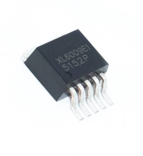
- Available in To-263 Package
Note: Complete Technical Details can be found at the XL6009 datasheet given at the end of this page.
XL6009 Equivalent
LT1070
Alternative Switching Regulators
LM2596, TPS5430, MC34063
XL6009 Introduction
Apart from providing higher or lesser output voltage than input voltage, the XL6009 Buck-Boost switching Regulator can also provide negative output voltages making it suitable for many analog applications. The Regulator can work both in Current Mode and DC/DC Converter mode and can be configured to work as Boost, Buck, Buck-Boost, Flyback, SEPIC or even as an inverting converter. A sample application circuit to make it work as boost converter is given below.
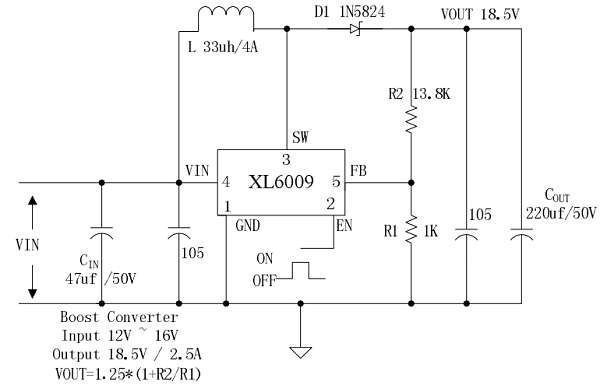
The input voltage to be regulated is provided to pin 4 and pin 1 is connected to ground. The enable pin is used to turn on (high) or off the device (low). By default the Enable pin will be considered to be high if left floating. An Inductor is connected between pin 3 and 4 which acts as an energy storage device. The switched output voltage can be obtained from pin 3.
A feedback of the output voltage is given to the Regulator IC through a potential divider to pin 5. Based on this feedback voltage value the PWM duty cycle for the N-Channel MOSFET (in-built) is adjust to control the output voltage. The value of Output voltage depends on the value of resistor R1 and R2 and can be given by the formulae
Vout = 1.25 * (1+(R2/R1))
Similarly application circuits are also given for other configuration circuits as well which can be found in the datasheet attached below.
Applications
- Buck Converter Circuit
- Boost Converter Circuit
- Buck-Boost Converter Circuit
- Battery Operated Applications
- Variable Voltage generators
- Miniature RPS Circuits
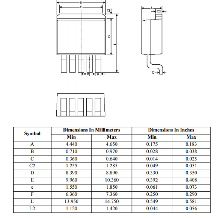
2D-Model