PIC16F887 Microcontroller

The PIC16F887 is an 8-bit microcontroller from Microchip. The 40-pin IC has 14 Channel 10-bit ADC making it suitable for applications which require more ADC inputs. The IC also has 2 Comparators, 2 Timers (8-bit and 16-bit) and supports SPI, I2C and UART communication protocols.
Features
|
PIC16F887 –Simplified Features |
|
|
CPU |
8-bit PIC |
|
Number of Pins |
40 |
|
Operating Voltage (V) |
2 to 5.5 V |
|
Number of I/O pins |
35 |
|
ADC Module |
14ch, 10-bit |
|
Timer Module |
8-bit(2), 16-bit(1) |
|
Comparators |
2 |
|
DAC Module |
Nil |
|
Communication Peripherals |
UART(1), SPI(1), I2C(1), MSSP(SPI/I2C) |
|
External Oscillator |
Up to 20Mhz |
|
Internal Oscillator |
8Mhz to 32KHz |
|
Program Memory Type |
Flash |
|
Program Memory (KB) |
14KB |
|
CPU Speed (MIPS) |
5 MIPS |
|
RAM Bytes |
368 |
|
Data EEPROM |
256 bytes |
Note: The PIC16F887 datasheet of the Microcontroller and more detailed Features can be found at the bottom of this page.
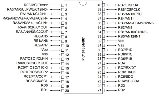
Pin Description
|
Pin Number |
Pin Name |
Description |
|
1 |
MCLR/Vpp/RE3 |
MCLR is used during programming, mostly connected to programmer like PicKit or 3rd pin of PORTE |
|
2 |
RA0/AN0 |
Analog pin 0 or 0th pin of PORTA |
|
3 |
RA1/AN1 |
Analog pin 1 or 1st pin of PORTA |
|
4 |
RA2/AN2/Vref- |
Analog pin 2 or 2nd pin of PORTA |
|
5 |
RA3/AN3/Vref+ |
Analog pin 3 or 3rd pin of PORTA |
|
6 |
RA4/T0CKI/C1out |
4th pin of PORTA |
|
7 |
RA5/AN4/SS/C2out |
Analog pin 4 or 5th pin of PORTA |
|
8 |
RE0/RD/AN5 |
Analog pin 5 or 0th pin of PORTE |
|
9 |
RE1/WR/AN6 |
Analog pin 6 or 1st pin of PORTE |
|
10 |
RE2/CS/AN7 |
Analog pin 6 or 2nd pin of PORTE |
|
11 |
Vdd |
Ground pin of MCU |
|
12 |
Vss |
Positive pin of MCU (+5V) |
|
13 |
RA7/OSC1/CLKI |
External Oscillator/clock input pin or 7th pin of PORTA |
|
14 |
RA6/OSC2/CLKO |
External Oscillator/clock output pin or 6th pin of PORTA |
|
15 |
RC0/T1OSO/T1CKI |
0th pin of PORT C |
|
16 |
RC1/T1OSI/CCP2 |
1st pin of POCTC or Timer/PWM pin |
|
17 |
RC2/CCP1 |
2nd pin of POCTC or Timer/PWM pin |
|
18 |
RC3/SCK/SCL |
3rd pin of POCTC |
|
19 |
RD0 |
0th pin of POCTD |
|
20 |
RD1 |
1st pin of POCTD |
|
21 |
RD2 |
2nd pin of POCTD |
|
22 |
RD3 |
3rd pin of POCTD |
|
23 |
RC4/SDI/SDA |
4th pin of POCTC or Serial Data in pin |
|
24 |
RC5/SDO |
5th pin of POCTC or Serial Data Out pin |
|
25 |
RC6/Tx/CK |
6th pin of POCTC or Transmitter pin of Microcontroller |
|
26 |
RC7/Rx/DT |
7th pin of POCTC or Receiver pin of Microcontroller |
|
27 |
RD4 |
4th pin of POCTD |
|
28 |
RD5/P1B |
5th pin of POCTD |
|
29 |
RD6/P1C |
6th pin of POCTD |
|
30 |
RD7/P1D |
7th pin of POCTD |
|
31 |
Vss |
Positive pin of MCU (+5V) |
|
32 |
Vdd |
Ground pin of MCU |
|
33 |
RB0/INT |
0th pin of POCTB or External Interrupt pin |
|
34 |
RB1/AN10 |
Analog pin 10 or 1st pin of POCTB |
|
35 |
RB2 /AN8 |
Analog pin 8 or 2nd pin of POCTB |
|
36 |
RB3/PGM/AN9 |
Analog pin 9 or 3rd pin of POCTB or connected to programmer |
|
37 |
RB4/AN11 |
Analog pin 11 or 4th pin of POCTB |
|
38 |
RB5/AN13 |
Analog pin 13 or 5th pin of POCTB |
|
39 |
RB6/PGC |
6th pin of POCTB or connected to programmer |
|
40 |
RB7/PGD |
7th pin of POCTB or connected to programmer |
Alternative for PIC16F887
PIC16F18877
Other PIC MCUs
PIC16F877A, PIC12F508, PIC12F629, PIC12F683, PIC16F505, PIC16F628A, PIC16F676, PIC16F72, PIC16F873A, PIC16F876A, PIC16F886, PIC18F252, PIC18F2520, PIC18F452, PIC18F4520
PIC16F887 Microcontroller Overview
The PIC16F887 is an 8-bit microcontroller from Microchip. The 40-pin IC has 14 Channel 10-bit ADC making it suitable for applications which require more ADC inputs. The IC also has 2 Comparators, 2 Timers (8-bit and 16-bit) and supports SPI, I2C and UART communication protocols.
It can operate at a speed of upto 20MHz with external oscillator and also has precision internal oscillator tunable between 8MHz to 32kHz. The IC supports nanoWatt technology allowing it to consume very low power and operate in Power-Saving sleep mode. It also have a wide operating voltage from 2V to 5.5V making it suitable for battery powered applications.
The IC also supports safety features like Power-on Reset (POR), Brown-out Reset (BOR), Low Current Watchdog Timer (WDT) etc making it suitable for task critical and industrial applications. The controller supports In Circuit Serial Programming (ICSP) allowing the designer to program the controller easily even without removing it from the actual circuit.
How to select your PIC Microcontroller
Microchip provides a wide verity of Microcontrollers from PIC family. Each MCU has its own advantage and disadvantage. There are many parameters that one has to consider before selecting a MCU for his project. The below points are just suggestions which might help one to select a MCU.
- If you are a beginner who is learning PIC then, selecting a MCU that has good online community support and wide applications will be a good choice. PIC16F877A and PIC18F4520 are two such MCUs
- Consider the operating voltage of your system. If they are 5V then select a 5V MCU some sensors or devices work and communicate on 3.3V in such case a 3.3V MCU can be selected
- If size and price is a limitation then you can choose small 8-pin MCUs like PIC12F508. These are also comparatively cheaper.
- Based on the sensors and actuators used in your project, verify which modules you might need in for MCU. For example is you are reading many Analog voltages then make sure PIC has enough ADC channels and supportive resolution. The details of all modules are given in the table above.
- If you project involves communication protocols like UART, SPI ,I2C, CAN etc make sure you PIC can support them. Some MCU can support more than one module of the same protocol
Programming PIC Microcontroller
PIC microcontroller can be programmed with different software's that is available in the market. There are people who still use Assembly language to program PIC MCUs. The below details is for most advanced and common software and compiler that has been developed by Microchip itself.
In order to program the PIC microcontroller we will need an IDE (Integrated Development Environment), where the programming takes place. A compiler, where our program gets converted into MCU readable form called HEX files. An IPE (Integrated Programming Environment), which is used to dump our hex file into our PIC MCUs.
IDE: MPLABX v3.35
IPE: MPLAB IPE v3.35
Compiler: XC8
Microchip has given all these three software for free. They can be downloaded directly from their official page. I have also provided the link for your convenience. Once downloaded install them on your computer. If you have any problem doing so you can post them on the comment below.
To dump or upload our code into PIC, we will need a device called PICkit 3. The PICkit 3 programmer/debugger is a simple, low-cost in-circuit debugger that is controlled by a PC running MPLAB IDE (v8.20 or greater) software on a Windows platform. The PICkit 3 programmer/debugger is an integral part of the development engineer's tool suite. In addition to this we will also need other hardware like Perf board or breadboard, Soldering station, PIC ICs, Crystal oscillators, capacitors etc.
Applications
- Design requiring many ADC channels
- Battery Operated Low Power applications
- Design requiring Multiple I/O interfaces and communications
- Ideal for more advanced level A/D applications in automotive, industrial, appliances and consumer applications.


