PIC16F676 – 8 bit Microcontroller
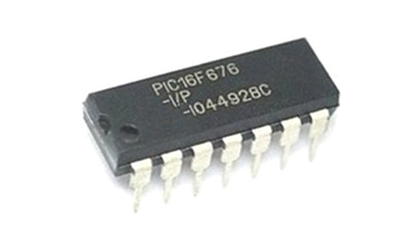
PIC16F676 is microcontroller from ‘PIC16F’ family and is made by MICROCHIP TECHNOLOGY. It is an 8-Bit CMOS Microcontroller and is very popular among hobbyists and engineers due its features, cost and small size.
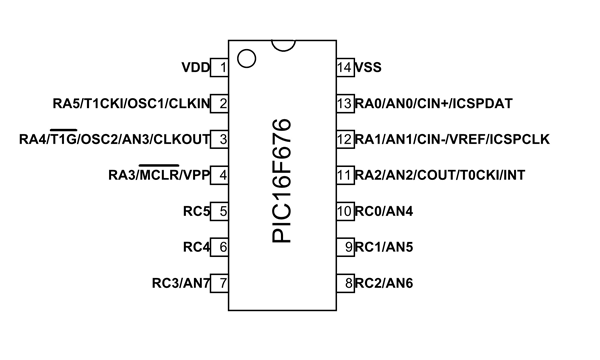
Pin configuration
PIC16F676 is a 14 pin device and many of them can perform multiple functions as shown in above pin diagram. The description for each of these functions is given below.
|
Pin |
Function |
Description |
|
1 |
VDD |
Positive Power Supply |
|
2 |
RA5/T1CKI/OSC1/CLKIN |
RA5: Pin5 of Port A T1CKI: Timer1 external clock input OSC1:Oscillator pin 1 CLKI: External clock source input |
|
3 |
RA4/T1G/OSC2/AN3/CLKOUT |
RA4: Pin4 of Port A T1G: Timer1 gate OSC2: Oscillator pin 2 AN3: Analog input 3 CLKO: Clock source output |
|
4 |
RA3/MCLR/VPP |
RA3: Pin3 of Port A MCLR: Master Clear Input or Reset pin VPP: Programming voltage |
|
5 |
RC5 |
RC5: Pin5 of Port C |
|
6 |
RC4 |
RC4: Pin4 of Port C |
|
7 |
RC3/AN7 |
RC3: Pin3 of Port C AN7: Analog input 7 |
|
8 |
RC2/AN6 |
RC2: Pin of Port C2 AN6: Analog input6 |
|
9 |
RC1/AN5 |
RC1: Pin of Port C1 AN5: Analog input5 |
|
10 |
RC0/AN4 |
RC0: Pin of Port C0 AN4: Analog input4 |
|
11 |
RA2/AN2/COUT/T0CKI/INT |
RA2: Pin2 of Port A AN2: Analog input2 COUT: Comparator output T0CKI: Timer0 clock input INT: External Interrupt |
|
12 |
RA1/AN1/CIN-/VREF/ICSPCLK |
RA1: Pin1 of Port A AN1: Analog input1 CIN-: Comparator input VREF: External Voltage reference ICSPCLK: Serial Programming Clock |
|
13 |
RA0/AN0/CIN+/ICSPDAT |
RA0: Pin0 of Port A AN0: Analog input0 CIN+: Comparator input ICSPDAT: Serial Programming Data I/O |
|
14 |
VSS |
Ground |
PIC16F676 Features and Electrical characteristics
|
CPU |
8-bit |
|
Total number of pins |
14 |
|
Programmable pins |
12 |
|
Communication Interface |
ICSP or In-Circuit Serial Programming Interface (13,14 Pins) [Can be used for programming this controller] |
|
ADC Feature |
8 channels of 10-bit resolution |
|
Timer Feature |
One 8-bit counter, One 16-bit counter |
|
PWM channels |
Not available |
|
Analog Comparator |
Available-1 |
|
External Oscillator |
Up to 20MHz |
|
Internal Oscillator |
4MHz Internal R-C Oscillator factory calibrated to ±1% |
|
Program memory / Flash memory |
2Kbytes[100000 write/erase cycles] |
|
CPU Speed |
1MIPS @ 1MHz |
|
RAM |
64bytes |
|
EEPROM |
128bytes |
|
Watchdog Timer
|
Available and is featured with Independent Oscillator for Reliable Operation |
|
Power Save Modes |
Available |
|
Operating Voltage |
2.0V to 5.5V |
|
Maximum current to any I/O pin |
IN :25mA OUT : 25mA |
|
Operating Temperature |
-40°C to +125°C |
|
Maximum current into VDD pin |
250mA |
PIC16F676 Replacement
PIC16F630
Similar Microcontrollers
PIC16F636, PIC16F684
PIC16F676 Microcontroller Overview
PIC16F676 is a microcontroller good for learning and experimenting for engineers because it has high flash memory rewrite cycle. The controller has 2KBytes flash memory which is enough for starters to develop basic programs. Also the 12 GPIO are designed for handling 20mA current (LED driving capability) by which beginners can connect peripheral at hand with less caution.
PIC16F676 has very few features and it cannot be used for developing advanced applications. It is used for developing small applications (like display driver) and for developing programs by beginners who want to enter microcontroller platform.
How to use PIC16F676 Microcontroller
Any microcontroller is needed to be programmed before installing in any system or application. So first we need to program the controller PIC16F676.
Entire process of programming PIC16F676 goes like this:
- First list all the functions to be executed by this controller.
- Next write these functions in ‘IDE software’ using ‘C’ language.
- This IDE software can be downloaded for free on company website.
- After writing the desired program compile it for error elimination.
- For a successful compilation IDE application generates HEX file for the written program.
- Choose the programming device (usually ‘PIC kit 3’ or ‘PIC kit 2’) which establishes communication between PC and PIC16F676.
- Connect the programming device to microcontroller appropriately.
- Run the HEX file dumping software which is related to the chosen programming device.
- Choose the appropriate program HEX file and burn this HEX file in PIC16F676 flash memory.
- Disconnect the programmer and connect the appropriate peripherals for the controller.
After connecting the power, the controller executes this HEX code saved in the memory (which is written program) and creates response as instructed.
Applications
- Beginner applications
- Hobbyist projects
- Display units
- Development board for learners
- Embedded systems like scrolling displays and meters
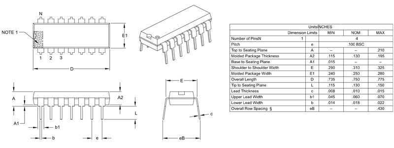
2D-Model