PIC16F628A 8-bit PIC Microcontroller

PIC16F628A is a CMOS FLASH-based mid-range 8-bit microcontroller that comes with an 18-Pin package, out of which, 16 pins can be used as I/O pins. This microcontroller has 4 Mhz of internal oscillator with 128 bytes of EEPROM data memory, packed with a single Capture/Compare/PWM, and a USART module with 2 comparators. Low voltage programming is supported by this microcontroller unit.
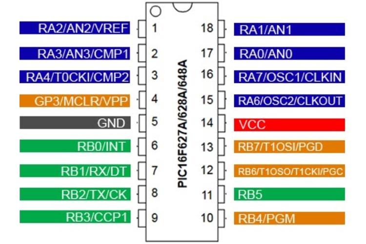
PIC16F628A Pin Configuration
|
Pin Number |
Pin Name |
Description |
|
1 |
RA2/AN2/VREF |
Bidirectional I/O pin of port A bit 2 or Analog comparator input channel 2 or Analog Voltage Reference output |
|
2 |
RA3/AN3/CMP1 |
Bidirectional I/O port or Analog comparator input or Comparator 1 output. |
|
3 |
RA4/T0CKI/CMP2 |
Bidirectional I/O pin of port A bit 4 or timer 0 clock input or comparator channel 2 output. |
|
4 |
RA5/MCLR/VPP |
Input port or Master clear or Programming voltage input. When configured as MCLR, this pin is an active-low Reset to the device, mainly used for Programming or Port A bit 5 Pin. |
|
5 |
VSS |
Power Ground pin. |
|
6 |
RB0/INT |
Bidirectional I/O pin of port B bit 0 or External interrupt pin. |
|
7 |
RB1/RX/DT |
Bidirectional I/O pin of port B bit 1 or USART Recieve pin or synchronous data I/O. |
|
8 |
RB2/TX/CK |
Bidirectional I/O pin of port B bit 2 or USART Transmit pin or synchronous clock I/O. |
|
9 |
RB3/CCP1 |
Bidirectional I/O pin of port B bit 3 or Capture compare PWM I/O. |
|
10 |
RB4/PGM |
Bidirectional I/O pin of port B bit 4 or Low voltage Programming pin. |
|
11 |
RB5 |
Bidirectional I/O pin of port B bit 5. |
|
12 |
RB6/T1OSC/T1CKI/PGC |
Bidirectional I/O pin of port B bit 6 or Timer1 Oscillator output or Timer1 Clock input or ICSP Programming clock mainly used for Programming purposes. |
|
13 |
RB7/T1OSI/PGD |
Bidirectional I/O pin of port B bit 7 or Timer1 Oscillator input or ICSP Programming data mainly used for Programming purposes. |
|
14 |
VDD |
Positive Power Pin. |
|
15 |
RA6/OSC2/CLKOUT |
Bidirectional I/O pin of port A bit 6 or Oscillator crystal output or Clock out in RC/INTOSC |
|
16 |
RA7/OSC1/CLKIN |
Bidirectional I/O pin of port A bit 7 or Oscillator crystal input or External Clock input |
|
17 |
RA0/AN0 |
Bidirectional I/O pin of port A bit 0 or Analog comparator input channel 0. |
|
18 |
RA1/AN1 |
Bidirectional I/O pin of port A bit 1 or Analog comparator input channel 1 |
Features and Specification of the PIC16F628A Microcontroller
|
PIC16F628A - Simplified Features and Specification |
|
|
CPU |
Mid-Range 8-bit |
|
Number of Pins |
18 |
|
Operating Voltage (V) |
2 - 5.5 V |
|
Number of I/O pins |
16 |
|
ADC Module |
Nil |
|
Timer Module |
3 |
|
Comparators |
2 |
|
DAC Module |
Nil |
|
Communication Peripherals |
UART(1) |
|
External Oscillator |
Yes |
|
Internal Oscillator |
4 MHz |
|
Program Memory (KB) |
3.5 KB |
|
CPU Speed (MIPS) |
5 |
|
RAM Bytes |
224 bytes |
|
Data EEPROM |
128 bytes |
Note: Complete technical details can be found in the PIC16F628A Datasheet linked at the bottom of this page.
Alternative for PIC16F628A
Alternative products for PIC16F628A microcontroller are listed below-
- PIC12F629
- PIC12F683
- PIC16F505
- PIC12F508
- PIC16F676
- PIC16F72
- PIC16F873A
- PIC16F876A
- PIC16F886
- PIC16F252
Other 8-bit Microcontroller
Introduction to PIC16F628A
PIC16F628A is a CMOS FLASH-based mid-range 8-bit microcontroller that comes with an 18-Pin package, out of which, 16 pins can be used as I/O pins. This microcontroller has 4 Mhz of internal oscillator with 128 bytes of EEPROM data memory, packed with a single Capture/Compare/PWM, and a USART module with 2 comparators. Low voltage programming is supported by this microcontroller unit.
PIC16F628A microcontroller also has two 8-bit and one 16-bit timer suitable for timing-related mid-range applications where different timers are required.
PIC16F628A works with 2V to 5.5V operations, thus it is suitable for 3.3V and 5.0V logic level applications. Brow-out Reset, Power-on Reset, Watchdog timer with an independent oscillator, Power-saving sleep modes are also supported by the PIC16F628A microcontroller. PIC16F628A pin mapping is shown below-
Detailed Features of PIC16F628A
|
PIC16F628A –Detailed Features |
|
|
CPU |
Mid-Range 8 - Bit |
|
Architecture |
8 - bit |
|
Program Memory Size (Kbytes) |
3.5 KB |
|
RAM (bytes) |
224 bytes |
|
EEPROM/HEF |
128 bytes |
|
Pin Count |
18 |
|
Max. CPU Speed (MHz) |
20 MHz |
|
Peripheral Pin Select (PPS) |
No |
|
Internal Oscillator |
4 MHz |
|
No. Of comparators |
2 |
|
No. Of Operational Amplifier |
Nil |
|
No. Of ADC channels |
Nil |
|
Max ADC Resolution (bits) |
- |
|
ADC with Computation |
No |
|
Number of DAC Converter |
Nil |
|
Max DAC resolution |
- |
|
Internal Voltage Reference |
2 - 5.5V |
|
Zero Cross Detect |
No |
|
No. Of 8-bit timers |
2 |
|
No. Of 16-bit Timers |
1 |
|
Signal Measurement Timer |
No |
|
Hardware Limit Timer |
No |
|
No. Of PWM outputs |
1 |
|
Max PWM resolution |
1024 |
|
Angular Timer |
No |
|
Math Accelerator |
No |
|
No. Of UART module |
1 |
|
No. Of SPI Module |
Nil |
|
No. Of I2C module |
Nil |
|
No. Of USB Module |
Nil |
|
Windowed Watchdog Timer (WWDT) |
No |
|
CRC/Scan |
No |
|
Numerically Controlled Oscillator |
No |
|
Cap. Touch Channels |
Nil |
|
Segment LCD |
Nil |
|
Minimum Operating Temperature (*C) |
-40°C |
|
Maximum Operating Temperature (*C) |
125°C |
|
Minimum Operating Voltage (V) |
2 V |
|
Maximum Operating Voltage (V) |
5.5V |
|
High Voltage Capable |
No |
Programming PIC Microcontroller
PIC microcontrollers can be programmed with different software that is available in the market. There are people who still use Assembly language to program PIC MCUs. The below details is for the most advanced and common software and compiler that has been developed by Microchip itself.
In order to program the PIC microcontroller, we will need an IDE (Integrated Development Environment), where the programming takes place. A compiler, where our program gets converted into MCU readable form called HEX files. An IPE (Integrated Programming Environment), which is used to dump our hex file into our PIC MCUs.
IDE: MPLABX v3.35
IPE: MPLAB IPE v3.35
Compiler: XC8
Microchip has given all these three software for free. They can be downloaded directly from their official page. I have also provided the link for your convenience. Once downloaded, install them on your computer. If you have any problem doing so, you can post them in the comment below.
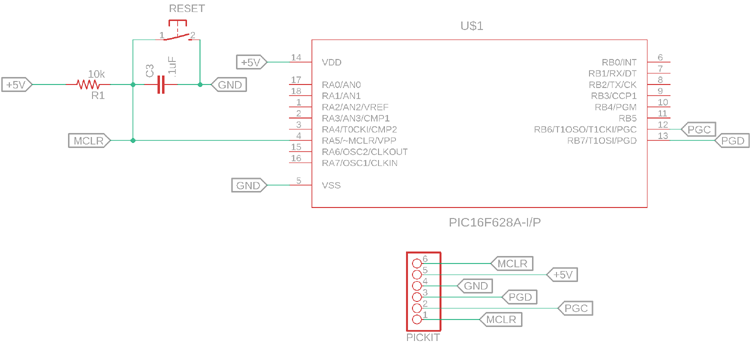
To dump or upload our code into PIC, we will need a device called PICkit 3. The PICkit 3 programmer/debugger is a simple, low-cost in-circuit debugger that is controlled by a PC running MPLAB IDE (v8.20 or greater) software on a Windows platform. The PICkit 3 programmer/debugger is an integral part of the development engineer's tool suite. A basic programming circuit for PIC16F628 is shown below.
In addition to this, we will also need other hardware like a Perf board or breadboard, Soldering station, PIC ICs, Crystal oscillators, capacitors, etc.
Components Associated with PIC
PICkit3, PIC Development Board, Crystal Oscillators, Capacitors, 12V Adapter, 7805 Voltage Regulator.
Application of PIC16F628A
This is a basic Mid-range 8-bit microcontroller unit that can be used in the following applications-
1. Input Output operations
2. Control Applications
3. Analog data Processing
4. Sensors integration and data logging
5. Small scale, low cost embedded application based production
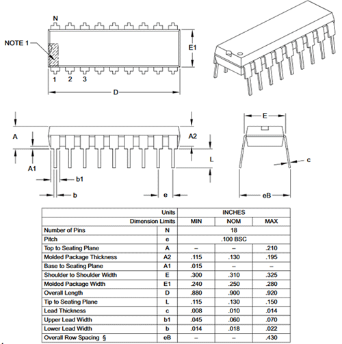
2D Model
The dimensions of the PIC16F628A are shown below-