BeagleBone Black
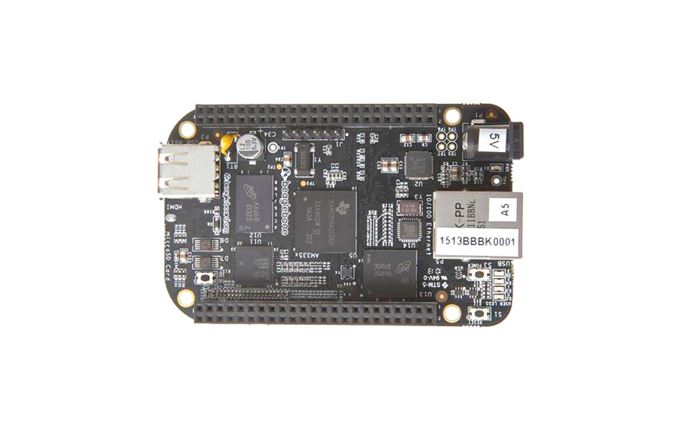
Beaglebone Black is no less than a computer. Yes, you read it right. It is packed with everything you find on a desktop or a laptop. A powerful processor, memory, and graphic acceleration, all shrunken down as chips and soldered into a single circuit board. Therefore, it is fair enough to call it a single-board computer.
This powerful microcontroller board can be hooked up with a display, speakers, Ethernet network, keyboard, and mouse. Moreover, it can be used to boot up a LINUX operating system.
It is a powerful tool for hobbyists and researchers to build sophisticated projects and a good approach to learning more about LINUX-based operating systems.
Similar Development Boards
Raspberry Pi, Arduino Yun, ARM LPC2129, Intel Edison, Beagle Bone Green.
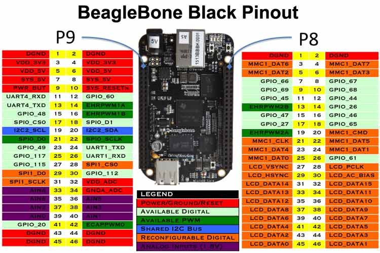
Beaglebone Black Pin Configuration
Each digital I/O pin has 8 different modes to choose from, including GPIO. Below are the BeagleBone Black Pinout tables for the P8 and P9 expansion headers of the Beaglebone black.
The PROC column is the pin number on the processor.
The MODE columns are the different mode settings available for each pin.
Please note that the MODE5 is missing because it really just doesn’t do anything. The only pin that works in MODE5 is GPIO0_7 in expansion header P9. It can be set as mmc0_swdp.
Expansion Header P8 Pinout
| PIN | PROC | NAME | MODE0 | MODE1 | MODE2 | MODE3 | MODE4 | MODE6 | MODE7 |
| 1,2 | GND | ||||||||
| 3 | R9 | GPIO1_6 | gpmc_ad6 | mmc1_dat6 | GPIO1[6] | ||||
| 4 | T9 | GPIO1_7 | gpmc_ad7 | mmc1_dat7 | GPIO1[7] | ||||
| 5 | R8 | GPIO1_2 | gpmc_ad2 | mmc1_dat2 | GPIO1[2] | ||||
| 6 | T8 | GPIO1_3 | gpmc_ad3 | mmc1_dat3 | GPIO1[3] | ||||
| 7 | R7 | TIMER4 | gpmc_advn_ale | timer4 | GPIO2[2] | ||||
| 8 | T7 | TIMER7 | gpmc_oen_ren | timer7 | GPIO2[3] | ||||
| 9 | T6 | TIMER5 | gpmc_be0n_cle | timer5 | GPIO2[5] | ||||
| 10 | U6 | TIMER6 | gpmc_wen | timer6 | GPIO2[4] | ||||
| 11* | R12 | GPIO1_13 | gpmc_ad13 | lcd_data18 | mmc1_dat5* | mmc2_dat1 | eQEP2B_in | GPIO1[13] | |
| 12* | T12 | GPIO1_12 | gpmc_ad12 | lcd_data19 | mmc1_dat4* | mmc2_dat0 | eQEP2A_in | GPIO1[12] | |
| 13* | T10 | EHRPWM2B | gpmc_ad9 | lcd_data22 | mmc1_dat1* | mmc2_dat5 | ehrpwm2B | GPIO0[23] | |
| 14* | T11 | GPIO1_26 | gpmc_ad10 | lcd_data21 | mmc1_dat2* | mmc2_dat6 | ehrpwm_tripzone | GPIO0[26] | |
| 15* | U13 | GPIO1_15 | gpmc_ad15 | lcd_data16 | mmc1_dat7* | mmc2_dat3 | eQEP2_strobe | GPIO1[15] | |
| 16* | V13 | GPIO1_14 | gpmc_ad14 | lcd_data17 | mmc1_dat6* | mmc2_dat2 | eQEP2_index | GPIO1[14] | |
| 17* | U12 | GPIO1_27 | gpmc_ad11 | lcd_data20 | mmc1_dat3* | mmc2_dat7 | ehrpwm0_synco | GPIO0[27] | |
| 18 | V12 | GPIO2_1 | gpmc_clk_mux0 | lcd_memory_clk | gpmc_wait1 | mmc2_clk | mcasp0_fsr | GPIO2[1] | |
| 19* | U10 | EHRPWM2A | gpmc_ad8 | lcd_data23 | mmc1_dat0* | mmc2_dat4 | ehrpwm2A | GPIO0[22] | |
| 20* | V9 | GPIO1_31 | gpmc_csn2 | gpmc_be1n | mmc1_cmd* | GPIO1[31] | |||
| 21* | U9 | GPIO1_30 | gpmc_csn1 | gpmc_clk | mmc1_clk* | GPIO1[30] | |||
| 22 | V8 | GPIO1_5 | gpmc_ad5 | mmc1_dat5 | GPIO1[5] | ||||
| 23 | U8 | GPIO1_4 | gpmc_ad4 | mmc1_dat4 | GPIO1[4] | ||||
| 24 | V7 | GPIO1_1 | gpmc_ad1 | mmc1_dat1 | GPIO1[1] | ||||
| 25 | U7 | GPIO1_0 | gpmc_ad0 | mmc1_dat0 | GPIO1[0] | ||||
| 26 | V6 | GPIO1_29 | gpmc_csn0 | GPIO1[29] | |||||
| 27* | U5 | GPIO1_22 | lcd_vsync* | gpmc_a8 | GPIO2[22] | ||||
| 28* | V5 | GPIO1_24 | lcd_pcik* | gpmc_a10 | GPIO2[24] | ||||
| 29* | R5 | GPIO1_23 | lcd_hsync* | gpmc_a9 | GPIO2[23] | ||||
| 30* | R6 | GPIO1_25 | lcd_ac_bias_en* | gpmc_a11 | GPIO2[25] | ||||
| 31* | V4 | UART5_CTSN | lcd_data14* | gpmc_a18 | eQEP1_index | mcasp0_axr1 | uart5_rxd | uart5_ctsn | GPIO0[10] |
| 32* | T5 | UART5_RTSN | lcd_data15* | gpmc_a19 | eQEP1_strobe | mcasp0_ahclkx | mcasp0_axr3 | uart5_rtsn | GPIO0[11} |
| 33* | V3 | UART4_RTSN | lcd_data13* | gpmc_a17 | eQEP1B_in | mcasp0_fsr | mcasp0_axr3 | uart4_rtsn | GPIO0[9] |
| 34* | U4 | UART3_RTSN | lcd_data11* | gpmc_a15 | ehrpwm1A | mcasp0_ahclkr | mcasp0_axr2 | uart3_rtsn | GPIO2[17] |
| 35* | V2 | UART4_CTSN | lcd_data12* | gpmc_a16 | ehrpwm1_tripzone | mcasp0_aclkr | mcasp0_axr2 | uart4_ctsn | GPIO0[8] |
| 36* | U3 | UART3_CTSN | lcd_data10* | gpmc_a14 | ehrpwm0_synco | mcasp0_axr0 | uart3_ctsn | GPIO2[16] | |
| 37* | U1 | UART5_TXD | lcd_data8* | gpmc_a12 | mcasp0_aclkx | uart5 _txd |
uart2_ctsn | GPIO2[14] | |
| 38* | U2 | UART5_RXD | lcd_data9* | gpmc_a13 | mcasp0_fsx | uart5_rxd | uart_rtsn | GPIO2[15] | |
| 39* | T3 | GPIO2_12 | lcd_data6* | gpmc_a6 | eQEP2_index | GPIO2[12] | |||
| 40* | T4 | GPIO2_13 | lcd_data7* | gpmc_a7 | eQEP2_strobe | pr1_edio_data_out7 | GPIO2[13] | ||
| 41* | T1 | GPIO2_10 | lcd_data4* | gpmc_a4 | eQEP2A_in | GPIO2[10] | |||
| 42* | T2 | GPIO2_11 | lcd_data5* | gpmc_a5 | eQEP2B_in | GPIO2[11] | |||
| 43* | R3 | GPIO2_8 | lcd_data2* | gpmc_a2 | ehrpwm2_tripzone | GPIO2[8] | |||
| 44* | R4 | GPIO2_9 | lcd_data3* | gpmc_a3 | ehrpwm_synco | GPIO2[9] | |||
| 45* | R1 | GPIO2_6 | lcd_data0* | gpmc_a0 | ehrpwm2A | GPIO2[6] | |||
| 46* | R2 | GPIO2_7 | lcd_data1* | gpmc_a1 | ehrpwm2B | GPIO2[7] |
*some pins are used by internal storage eMMC (11-21) and HDMI (27-46)
Expansion Header P9 Pinout
| PIN | PROC | NAME | MODE0 | MODE2 | MODE3 | MODE4 | MODE6 | MODE7 |
| 1,2 | GND | |||||||
| 3,4 | DC_3.3V | |||||||
| 5,6 | VDD_5V | |||||||
| 7,8 | SYS_5V | |||||||
| 9 | PWR_BUT | |||||||
| 10 | A10 | RESET_OUT | ||||||
| 11 | T17 | gpmc_wait0 | mii2_crs | gpmc_csn4 | rmii2_crs_dv | mmc1_sdcd | uart4_rxd_mux2 | gpio0[30] |
| 12 | U18 | gpmc_be1n | mii2_col | gpmc_csn6 | mmc_dat3 | gpmc_dir | mcasp0_aclkr_mux3 | gpio1[28] |
| 13 | U17 | gpmc_wpn | mii2_rxerr | gpmc_csn5 | rmii2_rxerr | mmc2_sdcd | uart4_txd_mux2 | gpio0[31] |
| 14 | U14 | gpmc_a2 | mii2_txd3 | rgmii2_td3 | mmc2_dat1 | gpmc_a18 | ehrpwm1A_mux1 | gpio1[18] |
| 15 | R13 | gpmc_a0 | gmii2_txen | rmii2_tctl | mii2_txen | gpmc_a16 | ehrpwm1_tripzone | gpio1[16] |
| 16 | T14 | gpmc_a3 | mii2_txd2 | rgmii2_td2 | mmc2_dat2 | gpmc_a19 | ehrpwm1B_mux1 | gpio1[19] |
| 17 | A16 | spi0_cs0 | mmc2_sdwp | I2C1_SCL | ehrpwm0_synci | gpio0[5] | ||
| 18 | B16 | spi0_d1 | mmc1_sdwp | I2CL_SDA | ehrpwm0_tripzone | gpio0[4] | ||
| 19 | D17 | uart1_rtsn | timer5 | dcan0_rx | I2C2_SCL | spi1_cs1 | gpio0[13] | |
| 20 | D18 | uart1_ctsn | timer6 | dcan0_tx | I2C2_SDA | spi1_cs0 | gpio0[12] | |
| 21 | B17 | spi0_d0 | uart2_txd | I2C2_SCL | ehrpwm0B | EMU3_mux1 | gpio0[3] | |
| 22 | A17 | spi0_sclk | uart2_rxd | I2C2_SDA | ehrpwm0A | EMU2_mux1 | gpio0[2] | |
| 23 | V14 | gpmc_a1 | gmii2_rxdv | rgmii2_rxdv | mmc2_dat0 | gpmc_a17 | ehrpwm0_synco | gpio1[17] |
| 24 | D15 | uart1_txd | mmc2_swdp | dcan1_rx | I2C1_SCL | gpio0[15] | ||
| 25 | A14 | mcasp0_ahclkx | eQEP0_strobe | mcasp0_axr3 | mcasp1_axr1 | EMU4_mux2 | gpio3[21] | |
| 26 | D16 | uart1_rxd | mmc1_sdwp | mcasp0_axr2 | I2C1_SDA | gpio0[14] | ||
| 27 | C13 | mcasp0_fsr | eQEP0B_in | mcasp1_fsx | EMU2_mux2 | gpio3[19] | ||
| 28 | C12 | mcasp0_ahclkr | ehrpwm0_synci | spi1_cs0 | eCAP2_in_PWM2_out | gpio3[17] | ||
| 29 | B13 | mcasp0_fsx | ehrpwm0B | spi1_d0 | mmc1_sdcd_mux1 | gpio3[15] | ||
| 30 | D12 | mcasp0_axr0 | ehrpwm0_tripzone | spi1_d1 | mmc2_sdcd_mux1 | gpio3[16] | ||
| 31 | A13 | mcasp0_aclkx | ehrpwm0A | spi1_sclk | mmc0_sdcd_mux1 | gpio3[14] | ||
| 32 | VADC | |||||||
| 33 | C8 | AIN4 | ||||||
| 34 | AGND | |||||||
| 35 | A8 | AIN6 | ||||||
| 36 | B8 | AIN5 | ||||||
| 37 | B7 | AIN2 | ||||||
| 38 | A7 | AIN3 | ||||||
| 39 | B6 | AIN0 | ||||||
| 40 | C7 | AIN1 | ||||||
| 41 | D14 | xdma_event_intr1 | tclkin | clkout2 | timer7_mux1 | EMU3_mux0 | gpio0[20] | |
| D13 | mcasp0_axr1 | eQEP0_index | mcasp1_axr0 | emu3 | gpio3[20] | |||
| 42 | C18 | eCAPO_in_PWM0_out | uart3_txd | spi1_cs1 | pr1_ecap0_ecap _capin_apwm_o |
spi1_sclk | xdma_event_intr2 | gpio0[7] |
| B12 | mcasp0_aclkr | eQEP0A_in | mcasp0_axr2 | mcasp1_aclkx | gpio3[18] |
- Up to 8, I/O pins can be configured with PWM (pulse width modulator) to generate signals to control motors without taking up any extra CPU cycle
- Pin number (32-40) in header P9 constitutes a single 12-bit analog-to-digital converter having 8 channels
- There are two I2C ports. The first I2C bus is utilized to read EEPROMS. It can also be used for other digital I/O operations without interfering with that function. The second I2C is available to configure according to the need of the user
- There are 2 SPI ports for fast shifting of data
- For advanced users, the Beaglebone black consists of 25 PRU low latency I/Os. They can make use 2 built-in 32 bit 200 MHz microcontrollers called PRU (Programmable Real-time Unit) in order to perform some real-time task
Beaglebone Black Technical Specifications
|
Processor |
Sitara AM3358BZCZ100 1 GHz, 2000 MIPS |
|
|
Graphics Engine |
SGX530 3D, 20M Polygons/S |
|
|
SDRAM Memory |
512MB DDR3L 800 MHz |
|
|
Onboard Flash |
4GB, 8-bit Embedded MMC |
|
|
PMIC |
TPS65217C PMIC regulator and one additional LDO |
|
|
Debug Support |
Optional Onboard 20-pin CTI JTAG, Serial Header |
|
|
Power Source |
miniUSB, USB or DC jack |
5V DC External Via Expansion Header |
|
PCB |
3.4” x 2.1” |
6 layers |
|
Indicators |
1-Power, 2-Ethernet, 4-User Controllable LEDs |
|
|
HS USB 2.0 Client Port |
Access to USB0, client mode via miniUSB |
|
|
HS USB 2.0 Host Port |
Access to USB1, Type A socket, 500 mA LS/FS/HS |
|
|
Serial Port |
UART0 access via 6-pin 3.3V TTL Header. Header is populated |
|
|
Ethernet |
10/100, RJ45 |
|
|
SD/MMC Connector |
microSD, 3.3V |
|
|
User input |
Reset button Boot button Power button |
|
|
Video out |
16b HDMI, 1280 x 1024 (MAX) 1024 x 768 x 1280 x 720, 1440 x 900, 1920 x 1080@24 Hz w/EDID Support |
|
|
Audio |
Via HDMI Interface, Stereo |
|
|
Expansion Connectors |
Power 5V, 3.3V, VDD_ADC(1.8V) 3.3V I/O on all signals McASP0, SPI1, I2C, GPIO(69 max), LCD, GPMC, MMC1, MMC2, 7 AIN(1.8V Max), 4 timers, 4 Serial Ports, CAN0, EHRPWM(0,2) , XDMA Interrupt, Power button, Expansion board ID (up to 4 can be stacked) |
|
|
Weight |
39.68 grams (1.4 oz) |
|
Note: More technical information can be found in the Beaglebone Black Datasheet, linked at the bottom of this page.
Difference between Beaglebone Black and Beaglebone
|
|
|
|
|
|
Beaglebone Black |
Beaglebone |
|
Processor |
AM3358BZCZ100, 1GHz |
AM3359ZCZ72, 720 MHz |
|
Video Out |
HDMI |
None |
|
DRAM |
512 MB DDR3L, 800MHz |
256MB DDR2, 400MHz |
|
Flash |
4GB eMMC , uSD |
uSD |
|
Onboard JT |
Optical |
Yes, over USB |
|
Serial |
Header |
Via USB |
|
PWR Exp Header |
No |
Yes |
|
Power |
210-460 mA@5V |
300-500 mA@5V |
Where is Beaglebone black used?
The Beaglebone Black is a pocket-friendly, compact development platform with excellent support from its fast-growing community. It is a perfect device for physical computing and smaller embedded applications.
The best feature of Beaglebone black which makes it a complete game changer is the feature to add different capes to it. Capes are plug-in boards that are added to Beaglebone black to enhance its functionality. Capes are available for motor control, VGA, camera, LCD, and other functionalities.
The Beaglebone Black can be used when–
- When you need to run heavy operating systems with low power
There are many scenarios during a DIY project when Arduino is not enough. For example, during the boot of the operating system and running heavy softwares, Arduino will require extra power. Here, Black comes in handy and does the same operation with low power.
- When your project needs a lot of hardware to be connected
In terms of GPIO connectivity, the Beaglebone black knocks out Raspberry Pi. In Pi, we have a single 26-pin header to be used as 8 GPIO pins or serial bus. However, in Beaglebone black, we can find two 48-socket headers using which we can connect virtually n number of I/O hardware. It also features a number of analog I/O pins to connect sensors which out-of-the-box Pi lacks.
- When you want your project to start quickly
Beaglebone black takes very less time to get up and running. It comes with pre-installed LINUX distro which saves a lot of time and prevents fuss.
How to get started with Beaglebone Black?
As mentioned earlier also, that getting started with Beaglebone black is a very quick and easy process.
- First, plug-in it into your computer using the included mini USB. This will power it up and boot into its LINUX distro, Angstrom
- Hook it up to a display and USB peripherals
- You can intall driver to connect Beaglebone black to web browser an dcontrol it with your computer
- From here, there are no limits. You can get acquainted with the LINUX operating system or write custom softwares for Beaglebone black using Python and libraries to manage all GPIOs
Applications
- Robotics
- Motor controller
- Controlling and monitoring using Display cape
- Automation
- IOT
- AWS
- Bluetooth connectivity projects
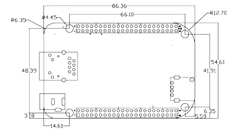
2D-Model and Dimensions