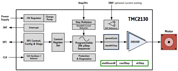
TMC2130 Motor Driver IC
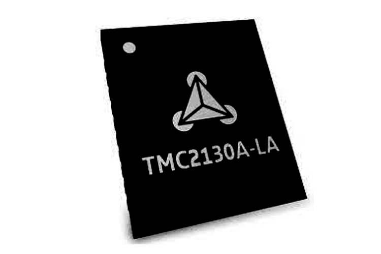
The TMC2130 is an integrated motor driver specifically meant for high voltage two-phase stepper motors with an SPI and STEP/DIR interface.
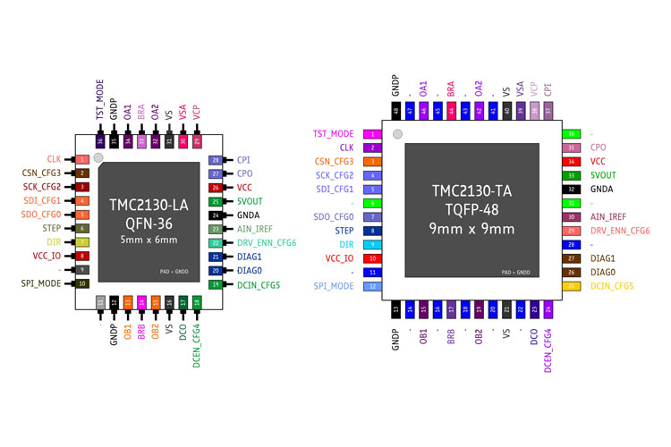
TMC2130 Pinout Configuration
|
Pin Number (QFN36) |
Pin Number (TQFP48) |
Pin Name |
Pin Description |
|
1 |
2 |
CLK |
CLK input, tie to ground for internal clock |
|
2 |
3 |
CSN |
SPI chip select input |
|
3 |
4 |
SCK |
SPI serial clock |
|
4 |
5 |
SDI |
SPI data input |
|
5 |
7 |
SDO |
SPI data output |
|
6 |
8 |
STEP |
STEP input |
|
7 |
9 |
DI |
DIR input |
|
8 |
10 |
VCC_IO |
IO supply for all digital pins, 3.3V to 5V |
|
9 |
11, 14, 16, 18, 20 22, 28, 41, 43, 45, 47 |
NC |
Do not connect |
|
10 |
12 |
SPI_MODE |
SPI pins mode select |
|
11 |
6, 31, 36 |
NC |
Connect to ground |
|
12, 35 |
13, 48 |
GNDP |
Power GND |
|
13 |
15 |
OB1 |
Motor coil B output 1 |
|
14 |
17 |
BRB |
Coil B sense resistor |
|
15 |
19 |
OB2 |
Motor coil B output 2 |
|
16, 31 |
21, 40 |
VS |
Motor supply voltage |
|
17 |
23 |
DCO |
dcStep ready output |
|
18 |
24 |
DCEN |
dcStep enable input |
|
19 |
25 |
DCIN |
dcStep gating input |
|
20 |
26 |
DIAG0 |
Diagnostics output |
|
21 |
27 |
DIAG1 |
Diagnostics output |
|
22 |
29 |
DRV_ENN |
Enable input |
|
23 |
30 |
AIN_IREF |
Analog reference |
|
24 |
32 |
GNDA |
Analog GND |
|
25 |
33 |
5VOUT |
5V output |
|
26 |
34 |
VCC |
5V input |
|
27 |
35 |
CPO |
Charge pump capacitor output |
|
28 |
37 |
CPI |
Charge pump capacitor input |
|
29 |
38 |
VCP |
Charge pump voltage |
|
30 |
39 |
VSA |
Analog supply |
|
32 |
42 |
OA2 |
Motor coil A output 2 |
|
33 |
44 |
BRA |
Coil B sense resistor |
|
34 |
46 |
OA1 |
Motor coil A output 1 |
|
36 |
1 |
TST_MODE |
Test mode input |
|
- |
- |
Die Pad |
Connect to GND |
Features and Specifications
- Drives two-phase stepper motors up to 2A, 2.5A peak
- STEP/DIR and SPI interface
- 4.75V to 46V supply range
- Current sensing option
- Passive braking
Note: Complete technical details can be found in the TMC2130 datasheet linked at the end of the page.
TMC2130 Equivalent
TMC2100, TMC2208, TMC5160
Other Motor Drivers
How To Use TMC2130 Motor Driver IC?
The TMC2130 is a 2-phase stepper motor driver that is capable of supplying up to 2A. It can communicate with an external microcontroller through an SPI and STEP/DIR interface.
It also integrates proprietary functions such as:
- stealthChop: a smoothing algorithm that makes movement and standstill inaudible
- spreadCycle: an algorithm for high dynamic motion and clean current waveform
- dcStep: load dependent speed control
- stallGuard2: sensorless stall detection and load measurement
- coolStep: load-dependent current consumption for high efficiency
- microPlyer: microstep interpolation to achieve smooth movement when using the STEP/DIR interface
The TMC2130 has three modes of operation:
- STEP/DIR Driver Mode
An external microcontroller generates STEP and DIRECTION signals.
The STEP input is in the form of pulses that controls motor movement, and the DIR signal indicates the movement direction.
- Standalone Mode
No external microcontroller is required and the movement is done using the STEP and DIR inputs. Configuration is done through the hardware pins.
- SPI Driver Mode
Operation in this mode is combined with the TMC4361 IC to provide full control over the motor current.
Applications
- Factory and lab automation
- 3D printers
- Pumps and valves
- Medical electronics
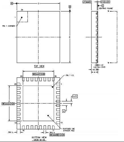
2D Model and Dimensions
If you are designing a PCB or Perf board with this component then the following picture from the Datasheet will be useful to know its package type and dimensions.