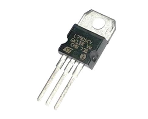
LM7905 Voltage Regulator
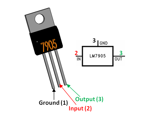
LM7905 Pin Description
|
Pin Number |
Pin Name |
Description |
|
1 |
Ground (Gnd) |
Unregulated Input Voltage |
|
2 |
Input (V+ |
Connected to Ground |
|
3 |
Output (Vo) |
Outputs Regulated -5V |
Features
- 5V Negative Voltage Regulator
- Output Voltage: -5V
- Output Current: 1.5A
- Minimum Input Voltage is 7V
- Maximum Input Voltage is 25V
- Operating current(IQ) is 5mA
- Internal Thermal Overload and Short circuit current limiting protection is available.
- Junction Temperature maximum 125 degree Celsius
- Available in TO-220 and KTE package
Note: Complete Technical Details can be found at the LM7905 voltage regulator datasheet given at the end of this page.
Alternative Regulator ICs
LM7806, LM7809, LM7812, LM317, LM7805, LM7912, LM117V33, XC6206P332MR.
Brief Description on 7905 Voltage Regulator
Voltage regulators are very common in electronic circuits. They provide a constant output voltage for a varied input voltage. In our case the 7905 IC is an negative 5V regulator, meaning it provides -5V as output. The name 7905 signifies two meaning, “79” means that it is a negative voltage regulator and “05” means that it provides 5V as output. So our 7905 will provide a -5V output voltage.
The output current of this IC can go up to 1.5A, but the IC suffers from heavy heat loss hence a Heat sink is recommended for projects that consume more current. For example if the input voltage is 12V and you are consuming 1A, then (12-5) * 1 = 7W. This 7 Watts will be dissipated as heat.
Why do we need Negative Voltage Regulators?
Negative voltage regulators are mainly used in Op-Amp and other circuits where a negative supply voltage is needed. In many cases where an Op-Amp is working in dual mode power supply a negative voltage will be regulated by these 79XX ICs. Also these IC’s will be able to source current into the ground rail instead of sinking it as normally
7905 as -5V Voltage Regulator
This is a typical application circuit of the 7905 IC. We just need two capacitors of vale 2.2uf and 1uf to get this IC working.
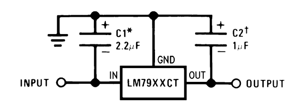
The input capacitor 2.2uF is a ceramic capacitor that deals with input inductance problem and the output capacitor 1uF is also a ceramic capacitor that adds to the stability of the circuit. These capacitors should be placed close to the terminals for them to work effectively. Also they should be of ceramic type, since ceramic capacitors are faster than electrolytic.
Applications
- Constant -5V output regulator to for op-amp signals
- Adjustable Output Regulator
- Current Limiter for certain applications
- Regulated Dual Supply
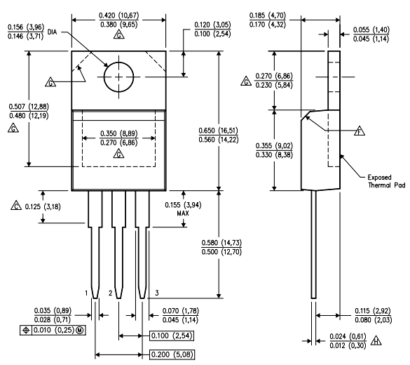
2D Model and Dimensions


3 Output (Vo) Outputs…
3 Output (Vo) Outputs Regulated +5V
-> -5V