Ceramic Capacitor
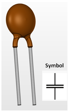
Pin Configuration
The Ceramic Capacitors has no polarity. Meaning they can be connected in any direction. They are breadboard friendly and can be easily used on a perf board also. The symbol for ceramic capacitor is just two plain lines as shown above since they do not have any polarity.
Note: There are many types of capacitors; however ceramic capacitors are the most widely used ones and this document is applicable only for the same.
Ceramic Capacitor Features
- Capacitor Type - Ceramic
- Has a high range of capacitance value starting from 10pF to 3.3uF
- Has a high range of voltage value starting from 16V to 450V
- Can withstand a maximum of 105°C temperature
Other Types of Capacitors
Ceramic Capacitor, Box Capacitor, Variable Capacitor, Mylar capacitors.
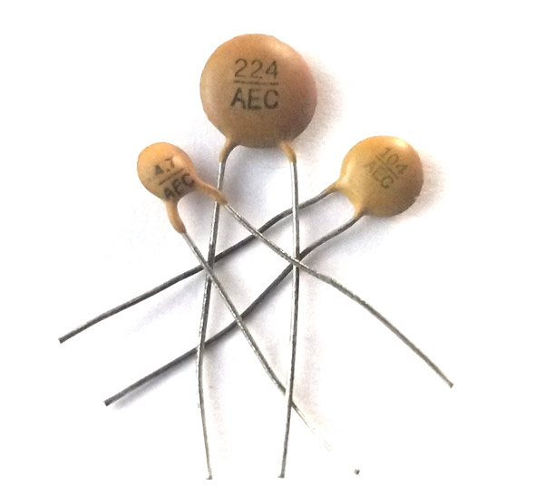
Identifying Ceramic Capacitors
The value of a ceramic capacitance will not be directly mentioned on the capacitor. There will always be a three digit number followed by a variable; let’s learn how to identify the value using these numbers. Consider the following capacitor.
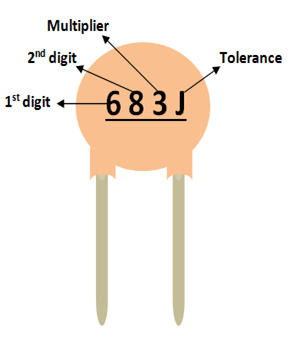
As you can notice, these three digits are split into two digits and the third one is the multiplier. In this case 68 is the digit and 3 is the multiplier. So 68 should be multiplied with 10^3. Simple put it is 68 followed by 3 zeros. Hence the value of this capacitor will be 68000 pF. Notice the unit should always be pF. Similarly a capacitor with 220 code means it is 22 Pico farad, since 10^0 is 0.
The voltage rating of the capacitor can be found by using the line under this code. If there is a line then the voltage value is 50/100V if there is no line then it is 500V.
The most commonly used capacitor values along with their conversion in Pico Farad, Nano Farad and microfarad is given below.
|
Code |
Picofarad (pF) |
Nanofarad (nF) |
Microfarad (uF) |
|
100 |
10 |
0.01 |
0.00001 |
|
150 |
15 |
0.015 |
0.000015 |
|
220 |
22 |
0.022 |
0.000022 |
|
330 |
33 |
0.033 |
0.000033 |
|
470 |
47 |
0.047 |
0.000047 |
|
331 |
330 |
0.33 |
0.00033 |
|
821 |
820 |
0.82 |
0.00082 |
|
102 |
1000 |
1.0 |
0.001 |
|
152 |
1500 |
1.5 |
0.0015 |
|
202 |
2000 |
2.0 |
0.002 |
|
502 |
5000 |
5.0 |
0.005 |
|
103 |
10000 |
10 |
0.01 |
|
683 |
68000 |
68 |
0.068 |
|
104 |
100000 |
100 |
0.1 |
|
154 |
150000 |
150 |
0.15 |
|
334 |
330000 |
330 |
0.33 |
|
684 |
680000 |
680 |
0.68 |
|
105 |
1000000 |
1000 |
1.0 |
|
335 |
3300000 |
3300 |
3.3 |
Capacitor parameters selection
Ever wondered about the types of ceramic capacitors available in market and how to select one for your project? ceramic capacitors can be classified based on two main parameters. One is their Capacitance(C-Farad) itself and the other is its Voltage (V-Volts) rating.
Capacitor is a passive component which can store a charge (Q). This charge (Q) will be a product of the value of capacitance (C) and the voltage (V) applied to it. The value of the capacitance and Voltage of a capacitor will be mentioned on its label.
Hence the amount of charge a capacitor can be found using the value of Voltage (V) and Capacitance (C) of the capacitor.
C = Q×V
Capacitor in series and parallel
In most of the circuits the value of the capacitance need not be exactly the same value specified in the circuit. A higher value of capacitance will generally not affect the performance of the circuit. However, the value of voltage should be the same or higher than the specified value to prevent the risk mentioned in precaution above. In that case, if you do not have the exact value you can use to capacitors in series or parallel to attain the desired value.
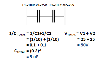
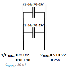
When two capacitors are connected in series then, the value of the capacitance(C) gets inversely added up and the rated voltage (V) is directly added up in series as shown in the picture below.
When two capacitors are connected in parallel then, the value of the capacitance(C) gets directly added up and the rated voltage (V) is remains the same in parallel as shown in the picture below.
Applications
- Filter circuits like High/Low pass filter etc.
- Remove noise from a circuit
- Smoothing ripples in converters
- Fading LED circuits
- Resonant circuits.
- Decoupling and by pass circuits
2D representation (Type F)
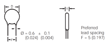
* Refer datasheet for values


