

Optimized with highly sensitive cap touch sensors, extensive peripheral circuits and 125℃ operation
What is Voltage Regulator and How Does It Work?
Most of the Integrated IC’s require a constant voltage with which it could operate. Be it a simple Logic Gate or a complex microprocessor they have their own operating voltage. The most common operating voltages are 3.3V, 5V and 12V. While we have batteries and DC Adaptors that could acts as a voltage source, most of the time they cannot be directly connected to our circuit design since the voltage from them is not regulated.
Say for example, we have 9V battery but need to trigger a 5V Relay, which obviously works on 5V. What do we do here?
What is Voltage Regulator and Why Do We Use It?
You recollect your school days we were taught that resistors drop voltage. Would it not be a simple fix to just use Resistors to drop the voltage according to Ohms Law? But then, resistors drop voltage depending on the current flowing through them. The moment your component starts drawing less current, the voltage shoots up and kills it.
You need something better – the voltage should not depend on the load current, at least not much. The next simplest fix that comes to your head is the voltage divider. This needs two resistors, but hey, if they can be squeezed in they may as well work. Another nagging problem – the moment your component starts drawing too much current, the output of the divider sags – the top resistor is not able to keep up with the current demand. Now you really start wishing you’d learnt about this in school. You could fix this by lowering the resistor values, but that would make the two resistors draw too much current, probably ruining your current budget and getting too hot with the immediate risk of failure.
What else could be done? Amplification! Of course, you had to slog through hours of lectures on those! Why not add an NPN transistor as a voltage follower? The voltage divider bias could be connected to the base, the 12V rail input to the collector and the output to the component to the emitter, and bingo, you’ve solved the problem!
Of course, the fix works, but it leaves you with a nagging feeling – you’ve used three parts, and on testing you find out that glitches in the 12V supply rail are replicated perfectly on the output. Of course, this is an amplifier, it does not have the intelligence to auto-compensate. You could replace the bottom resistor of the voltage divider with a Zener diode, but the current required to properly bias a Zener (against things like temperature coefficients and drift) is almost as much as your component consumes – which is completely pointless.
Isn’t there a better way to do this? Isn’t there a magic black box that contained everything needed to drop a voltage efficiently? Millions of EEEs around the world have been though similar periods of stress (including me!). Of course, not all problems are associated with dropping voltages, but similar situations are common is EEE labs everywhere!
But you’re in luck – the exact component you need exists. In fact, it’s one of the earliest commercial implementation of the IC technology (apart from op-amps) – the humble voltage regulator.
If you ever look through the datasheet of a voltage regulator, you’ll be amazed at the circuitry they’ve been packed with to drop a voltage and keep it clean – a nice stable voltage regulator, amplifiers with feedback and compensation and a half – decent power stage. Of course, if we’ve been able to pack so much technology into those phones of ours, why not some voltage regulation into a nice TO – 92 package?
They keep getting better every day – some of them consume no more than a few nanoamps, that is a thousandth of a millionth of an amp! Even better, others come with short circuit and overtemperature protection – making them foolproof.
Voltage Regulators - A Closer Look
As we’ve seen in the section above, the primary job of a voltage regulator is to drop a larger voltage to a smaller one and keep it stable, since that regulated voltage is being used to power (sensitive) electronics.
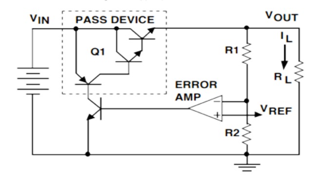
A voltage regulator is basically a beefed up emitter follower, like described above – a transistor connected to a stable reference that spits out a constant voltage, dropping the rest.
They also have a built in error amplifier, which samples the output voltage (again through a divider), compares it with the reference voltage, calculates the difference, and drives the output transistor accordingly. This is far cry from a voltage divider, which faithfully replicates the input signal, though just a magnitude smaller. You don’t want AC ripple overlaid on your DC voltage rail.
It is desirable to have a transistor with high gain, since power transistors are a huge pain to drive, with pathetic gains in the range of two digits. This has been overcome by using Darlington transistors and more recently MOSFETs. Since these types require less current to drive, the overall current consumption decreases. This is supplemented by the fact that the voltage reference used internally also consumes very little current.
The current that the regulator consumes to drive all this internal circuitry when the output is not loaded is called the quiescent current. The lower the quiescent current, the better.
The way these regulators are built has three transistors on the power output stage – two of them in a Darlington configuration and the other as a current limiting device. The successive CE junctions add up to a voltage drop of around 2V across the regulator.
This voltage is known as the dropout voltage, the voltage below which the regulator quits regulating.
You can find devices called LDOs or low dropout regulators with a voltage drop of around 0.4V, since they use a MOSFET switch.
Three Terminal Regulators
Enough talk, now for the actual part numbers.
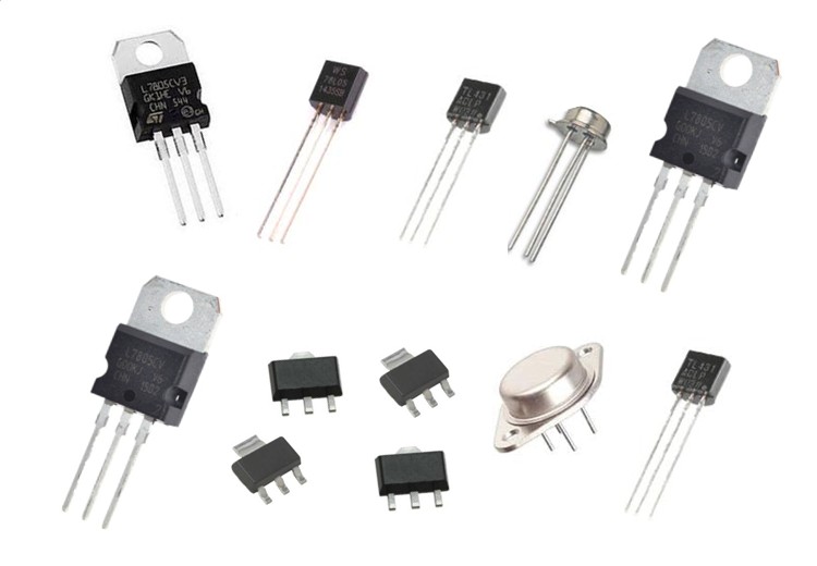
The most common series of voltage regulators is the 78XX series. The two digits after the 78 represent the output voltage of the regulator, for example the 7805 is a 5V regulator and the 7812 is a 12V regulator. The output voltages available with fixed regulators covers a large range from 3.3V to 24V with nice values like 5V, 6V, 9V, 15V and 18V available.
This series of regulators are excellent for most purposes, they can handle up to almost 30V on the input and depending on the package, up to 1A output current. They’re exceptionally simple to use – connect the input pin to the input voltage and the output pin to the device that needs the lower voltage and, of course, the ground pin to ground.
Here decoupling capacitors are optional, since the feedback amplifiers ‘reject’ input ripple and noise, making sure that they do not pass on to the output. However, if your device draws more than a few tens of milliamps, at least 4.7uF on the input and output is recommended, preferably in ceramic.
An interesting thing people do is make primitive phone chargers using these regulators. Simply connect a 9V battery to the input and an appropriate USB connector to the output and voila, you’ve got yourself an emergency phone charger. This construction is quite robust, because of the built in thermal protection on the chip.
A nice thing about these kinds of voltage regulators is that the pinouts are almost universal, so plug in replacements are possible. Nowadays most of the ‘transistor’ packages on PCBs are voltage regulators which can be picked up for other projects because they are so easy to use.
Increasing the Output Current of Voltage Regulators
One limitation that quickly overcomes the usefulness is the output current, which is severely limited by the package and the way that the package is mounted.
There are high current variants of these regulators but they are hard to find.
The only devices capable of spitting out high currents are DC-DC switching converters, but the output noise figures are terrible.
Designing your own high current linear regulator is possible, but you’ll eventually run into all the problems mentioned above.
Luckily, there is a way to ‘hijack’ a standard regulator with a few additional parts and increase the output current.
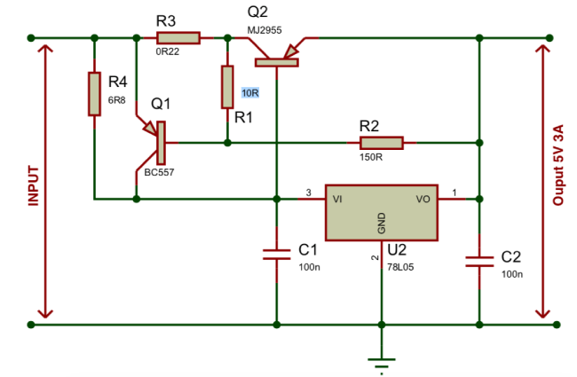
Most of these modifications involve adding a bypass transistor across the regulator and driving the base with the input, like shown in the below figure.
Adjustable Regulators
Three terminal regulators are quite nice and easy to use, but what if you want a non-standard output voltage like 10.5V or 13V?
Of course it is more or less possible to hijack fixed regulators, but the required circuitry is quite complex and beats the primary purpose of simplicity.
Devices exist which can do the job for us, the most popular being the LM317.
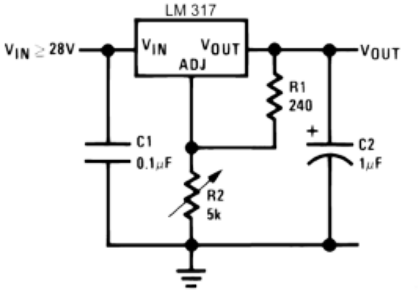
The LM317 is just like any other linear regulator with an input and an output pin, but instead of a ground pin there’s a pin called ‘adjust’. This pin is designed to get feedback off of a voltage divider across the output so that the pin is always at 1.25V, by varying the resistance values we can obtain different voltages. The datasheet even says, ‘eliminates stocking many fixed voltages’, but of course this applies only if you can afford to have those two resistors on board.
A nice thing about adjustable regulators like this is that with a small change in configuration they can serve as constant current supplies too.
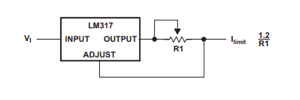
By connecting a resistor to the output pin and the adjust pin to the other end of the resistor like shown in the figure, the regulator tries to maintain a constant 1.25V across the output resistor and hence a constant current on the output. This simple circuit is quite popular with the diode laser community.
Fixed regulators can do this too, but the dropout voltages are unreasonably high (in fact, the rated output voltage). They will work in a pinch, however, if you’re desperate.
Voltage Regulator Limitations
The biggest advantage of linear regulators is their simplicity; nothing else needs to be said.
However, like all good chips they come with their own set of limitations.
Linear regulators work like a variable resistor with feedback, dropping any unneeded voltage. While drawing the same current as the load. This wasted energy is converted to heat, making these regulators hot and inefficient at high currents.
For example, a 5V regulator with a 12V input running at 1A has a power loss of (12V – 5V)*1A, which is 7W! That is a lot of wasted energy, and the efficiency is only 58%!
So at high input-output voltage differentials or at high currents, regulators have a pathetic energy efficiency.
The input-output differential voltage problem can be overcome using more than one regulator in series with decreasing output voltages (up to the desired voltage value) so that the voltage is dropped in steps. While the overall power dissipation is the same as having one regulator, the heat load is spread out across all the devices, decreasing overall operating temperature.
The power and efficiency limitations can be overcome by using a switching supply, but the choice is application dependent, there are no clear cut rules as to where to use which type of power supply.


