

Optimized with highly sensitive cap touch sensors, extensive peripheral circuits and 125℃ operation
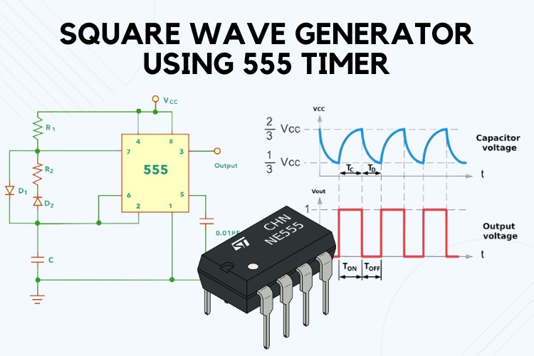
How to Generate Sqaure Wave Signal using 555 Timer IC
A square wave generator is an essential tool in electronics, capable of producing square waves for various applications, including timing circuits, clock signals, and waveform generation. One of the most common ways to create a square wave generator is by using the versatile 555 timer IC. In this article, we will explore how to use the 555 timer to generate square waves, including adjustable frequency and duty cycle. We'll cover the circuit design, calculations, advantages, and applications, and provide practical tips for implementing the circuit.
What is a square wave generator?
A square wave generator is an electronic circuit that produces a square waveform. A square waveform is a type of non-sinusoidal waveform that alternates between a high and a low state at a consistent frequency, creating a pattern that looks like a series of squares when viewed on an oscilloscope. The square wave has two distinct levels, typically representing a binary high (1) and low (0), making it ideal for digital and timing applications.
Introduction to 555 Timer
The 555 timer IC is a highly reliable and versatile integrated circuit used in a wide range of applications, from simple timers to complex waveform generators. It operates in three modes: astable, monostable, and bistable. For generating square waves, we use the astable mode, also known as the free-running or astable multivibrator mode. In this mode, the 555 timer continuously oscillates between its high and low states, producing a square wave output. To learn more about the 555 timer IC please check our comprehensive guide to 555 Timer article.
555 Square Wave Generator Circuit Design
Here is a simple 555 timer astable multivibrator circuit.
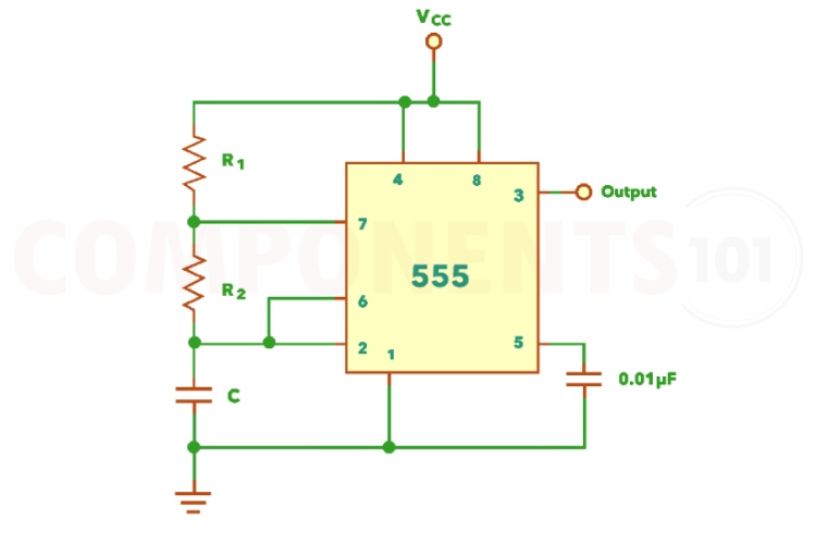
The IC 555 can be made to work as an astable multivibrator with the addition of three external components: two resistors (R1 and R2) and a capacitor (C). The supply pin 8 and reset pin 4 are connected to the supply voltage, pin 1 to ground and pin 5 is connected to ground via a 0.01uF capacitor. The pins 2 and 6 are connected and hence there is no need for an external trigger pulse. It will self-trigger and act as a free-running multivibrator (oscillator). Pin 3 is the output terminal and hence the output is available at this pin. The timing circuit that determines the width of the output pulse is made up of R1, R2 and C.
555 Squarewave Generator Working
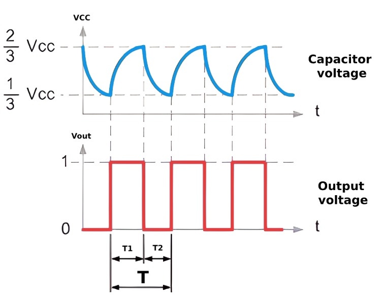
Initially, on power-up, the 555 timer's flip-flop is reset, making the output low and causing the discharge transistor to saturate, discharging the capacitor through the transistor. When the capacitor voltage drops below 1/3 VCC, the timer output goes high, turning off the transistor and allowing the capacitor to charge through resistors R1 and R2. As the capacitor voltage exceeds 2/3 VCC, the flip-flop resets, the output goes low, and the discharge transistor turns on, discharging the capacitor again. This cycle repeats, producing a train of rectangular pulses at the output. Here is the waveform for the circuit, the blue wave indicates the charging curve of the timing capacitor C and the red one is the output waveform.
Frequency Calculation for 555 Timer
The frequency (f) and of the output the output can be calculated using the following formulas: Frequency f= 1.44(R1+2R2)C1 You can also take advantage of our online 555 Timer Astable Circuit Calculator to do the same. You can learn more details about the free running frequency from our Free Running Frequency of Astable Multivibrator article.
Creating True Squarewave
To achieve a true square wave output with a 50% duty cycle using a 555 timer in an astable multivibrator mode, modifications to the standard circuit are necessary because the basic design results in a duty cycle greater than 50%. By adding two diodes to the circuit, this limitation can be overcome.
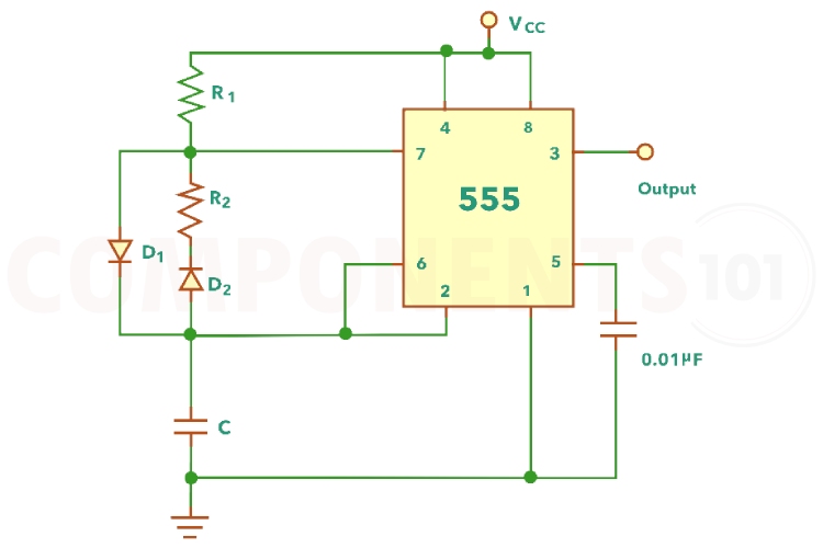
One diode is placed in parallel with resistor R2, with its cathode connected to the capacitor, and another diode is placed in series with resistor R2, with its anode connected to the capacitor. These modifications allow the capacitor to charge and discharge through different paths, thereby enabling precise control over the duty cycle. Adjusting the values of resistors R1 and R2 allows for fine-tuning, making it possible to achieve a duty cycle ranging from 5% to 95%, including the exact 50% required for a square wave output. This simple yet effective modification enhances the versatility of the 555 timer in generating precise square waveforms. In this circuit, while charging, the capacitor charges through R1 and D1 by passing R2. While discharging, it discharges through D2 and R2.
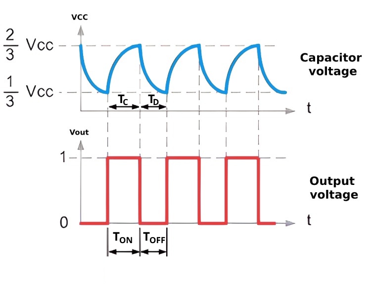
Therefore, the charging time constant is TON=TCand is given by: TON=0.693R1C And the discharging time constant TOFF=TDis given by: TOFF=0.693R2C Therefore, the duty cycle D is given by: D=R1R1+R2 In order to get a square wave, the duty cycle can be made 50% by making the values of R1 and R2 equal. The waveforms of the square wave generator are shown below.
Advantages of 555 Sqaure Wave Generator
One of the main advantages of using a 555 timer for generating square waves is its simplicity. The circuit design is straightforward and easy to implement, making it suitable for beginners and experienced electronics enthusiasts alike. Additionally, the 555 timer IC and other required components are inexpensive and widely available, making the project cost-effective. The adjustability of the square wave generator is another significant advantage; by using variable resistors, both the frequency and duty cycle can be fine-tuned to meet specific requirements. Furthermore, the 555 timer IC is known for its stability and reliability, ensuring consistent performance in various applications. Its versatility allows it to be used in a wide range of applications, from basic timing circuits to complex waveform generators.
Applications of Sqaure Wave Generator
- Clock signals for digital circuits
- Pulse Width Modulation (PWM) signals
- Square wave audio signals
- Frequency modulation in communication systems
- Tone generation in audio equipment
- Signal testing in laboratory equipment
- LED and motor driver circuits for varying brightness and speed


