

Optimized with highly sensitive cap touch sensors, extensive peripheral circuits and 125℃ operation
Free Running Frequency of Astable Multivibrator

An astable multivibrator circuit continuously oscillates without requiring any external trigger, making it useful for generating periodic signals in electronic devices. The free-running frequency of an astable multivibrator depends on the values of its capacitors and resistors. So, in this article, we will learn how to calculate the free-running frequency.
What is an Astable Multivibrator
An astable multivibrator is a type of oscillator circuit that continuously switches between its two unstable states without requiring any external triggering. This characteristic makes it a fundamental component in creating clock pulses, timing circuits, and light flashers, among other applications. Unlike its counterparts—the monostable and bistable multivibrators—astable circuits do not have a stable state, which is why they are often referred to as free-running oscillators.
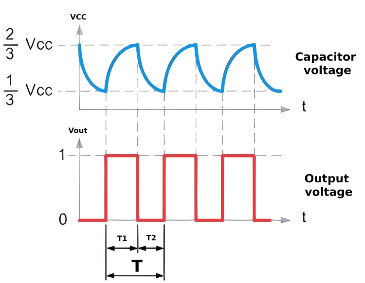
In the image below you can see two waveforms, the top one represents the timing capacitor voltage, and the bottom one represents the output voltage of an astable multivibrator. As you can see the output voltage is alternating in between the LOW and HIGH state. The output will continue to do so, effectively generating a square wave output until the power is disconnected.
How Astable Multivibrator Works
The operation of an astable multivibrator relies on the charging and discharging cycles of capacitors connected to its circuit. Typically, the circuit includes two amplifying elements configured in a feedback loop, which could be transistors, operational amplifiers, or comparators. Each component—capacitors and resistors—plays a critical role in determining the timing interval of the oscillations. The switching from one state to another and back again is what generates a continuous square wave output, which is essential for various digital circuits. Since the output of an Astable multivibrator continuously oscillates between two different output voltage levels without any control or trigger the output waveform appears to be free running. This is why sometimes an Astable Multivibrator is also called as a Free Running Multivibrator.
Before we try and understand free running frequency let's look at a simple Astable Multivibrator Circuit to understand how it works.
Basic Astable Multivibrator Circuit
A basic astable multivibrator can be constructed using two transistors and a few resistors and capacitors. The image below shows the circuit diagram of a simple Astable Multivibrator.
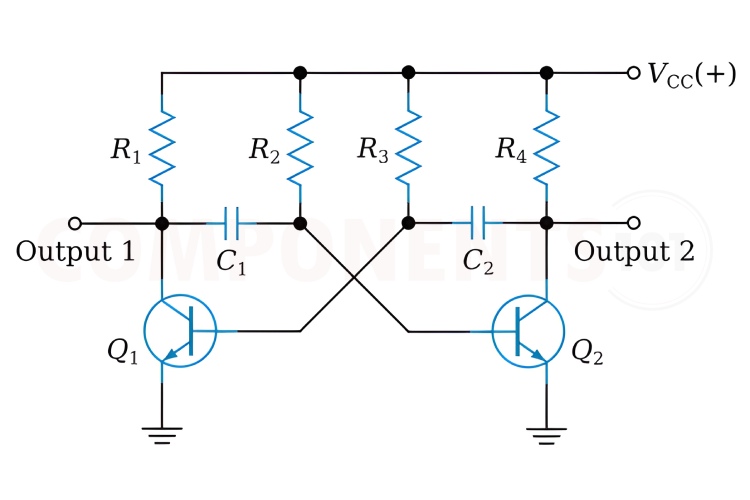
The astable multivibrator, shown in the above circuit diagram, is basically two amplifier circuits arranged with regenerative feedback. One of the amplifiers is conducting while the other is cut off, this continues in a loop, thus creating an oscillation. The resistor R3 and capacitor C2 determine the timing for transistor Q1 and resistor R3 and capacitor C2 determine the timing for transistor Q2.
As you can see in the above simulation, the output oscillates continuously. The yellow dots indicate the current flow. The green line indicates that the voltage is flowing to that section indicating charging, and the red line indicates that the current is flowing from that section indicating discharging.
Initially, let’s assume that transistor Q1 is turned on at first. The capacitor C1 connected to the collector of Q1 starts charging through a resistor from the supply voltage. The charging of C1 eventually increases the base voltage of Q2. Once the voltage across C1 reaches a sufficient level, it turns on Q2. The turning on of Q2 causes its collector voltage to drop, which starts discharging the capacitor C2, thus decreasing the base voltage of Q1, and eventually turning it off. This increases the collector voltage of Q1, which, in turn, helps charge capacitor C2 connected to Q2. As C2 charges, it reaches a point where it provides enough base voltage to Q1 to turn it on again, thereby turning Q2 off as its base voltage is pulled low through C1 now discharging. This cycle continues indefinitely as long as the circuit is powered. Each transistor alternates between on and off states, creating a square wave output at each collector.
An astable multivibrator can also be constructed using timer chips like NE555 or dedicated multivibrator ICs like CD4047. This article only discusses the theory of Free Running Frequency of an Astable Multivibrator. If you want to build an Astable multivibrator you can check out this 555 Timer based Astable Multivibrator and Op-Amp based Astable Multivibrator
Calculating free-running Frequency of Astable Multivibrator
The free-running frequency of an astable multivibrator is the rate at which it oscillates between its two states. This frequency can be calculated using the formula: As we know total time period
T = T1+T2
Where T1 = 0.69R2C1, and T1 = 0.69R3C2.
If the value of the capacitor C1 equals the value of the capacitor, C2, C1 = C2 and also the value of the base resistor R2 equals the value of the base resistor, R3, R2 = R3 then the total length of time of the Multivibrators cycle is given below for a symmetrical output waveform. So the time period can be calculated as T = 1.38RC So now that we have calculated the time period, the formulae for free-running frequency can be given as
f = 1T = 11.38RC
Note: R is in Ω’s and C in Farads. For example, if we substitute the values of R and C with the ones we have used for the simulation f= 11.38RC=11.3810000.000018=40.257Hz40Hz And this can be verified from the above simulation.
Applications and Importance of Free Running Frequency
The flexibility and simplicity of astable multivibrators make them indispensable in the field of electronics. They are widely used in pulse generation, timers, LED flashers, and alarm circuits. The ability to adjust the free running frequency by tweaking component values enables designers to tailor the behavior of the multivibrator to meet specific operational requirements. This adaptability, combined with the ease of setup, underscores the utility and relevance of astable multivibrators in both amateur and professional electronic projects.


