

Optimized with highly sensitive cap touch sensors, extensive peripheral circuits and 125℃ operation
Comprehensive Guide to 555 Timer with Pinout, Specs, and Operating Modes
The 555 timer is one of the most versatile and widely used integrated circuits (ICs) in electronics. Since its invention in the 1970s, has stood the test of time due to its reliability, simplicity, and multifaceted applications. Let's look into a detailed understanding of its pinout, key specifications, and the various modes of operation.
555 Timer Pinout
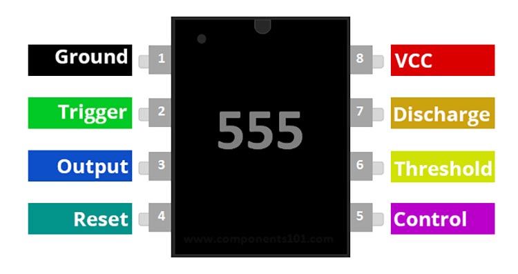
- Ground (GND): This is the reference voltage against which all other voltages are measured. It connects to the circuit's ground or the negative terminal of the power supply.
- Trigger (TRIG): When a voltage on this pin drops below half of the control voltage (typically 1/3 of the VCC if the control voltage is not externally defined), the output becomes high and the timer activates.
- Output (OUT): This pin can either source or sink current. It’s the main output of the timer. Depending on the mode of the 555 timer, the output pin might produce a continuous square wave (Astable mode) or a single pulse width (Monostable mode).
- Reset (RESET): When a negative pulse is applied to this pin, the timer resets and the output goes low. If the reset functionality isn't required in a circuit, this pin is typically connected to VCC to prevent unintended resets.
- Control Voltage (CV): An external voltage applied to this pin can be used to modulate the threshold and trigger levels. If not being used for modulation, a small ceramic capacitor (like 0.01μF) is typically connected to ground to filter noise.
- Threshold (THRESH): Compares the voltage applied to it to a reference voltage (usually 2/3 VCC). In many timer circuits, this pin is directly connected to the external capacitor that dictates the timing of the circuit.
- Discharge (DISCH): Connected internally to an NPN transistor, this pin is primarily used to discharge the external timing capacitor.
- VCC: This pin powers the 555 timer and can typically accept voltages between 4.5V and 15V.
Specifications:
- Supply Voltage (VCC): 4.5V to 15V, though some low-power variants can operate on voltages as low as 2V.
- Operating Temperature: Generally, between -55°C to 125°C.
- Output Drive Capability: 200mA, allowing it to drive peripheral devices directly, including LEDs or small speakers.
- Timing Range: Extremely versatile, the 555 can produce time delays ranging from microseconds to hours.
Overall Operation
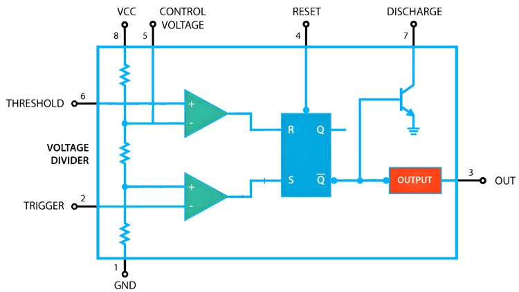
Internally, the 555 chips layout can be visualized as a block diagram featuring 2 comparators, a flip-flop, a voltage divider, a discharge transistor, and an output stage. This voltage divider, in particular, comprises three 5k resistors, setting two reference voltages at 1/3 and 2/3 of the supplied voltage (which varies between 5 and 15V). Comparators within the 555 Timer act as voltage comparison units; their function is to compare analog inputs and produce outputs accordingly. The interaction between the "Trigger," "Threshold," and "Control" pins directly influences the comparators' output. This output is channelled into a flip-flop, which toggles based on the input conditions and can be overridden using an external “Reset” pin. Concluding the internal setup, the flip-flop’s output feeds into drivers capable of managing up to 200mA and a transistor connecting the "Discharge" pin to the ground.
Operating Modes
Astable Mode:
In this free-running mode, the 555 timer oscillates endlessly, transitioning between its high and low states, producing a continuous square wave output. This makes it apt for applications like tone generation and LED blinking.
Monostable Mode
The 555 timer in this mode functions as a one-shot timer. It remains in its low state until triggered, after which it produces a high pulse for a defined period and then reverts to its low state.
Bistable Mode
This mode transforms the 555 timer into a basic flip-flop, a digital memory device. It has two stable states (high and low) and can maintain either until externally altered.
The 555 timer's lasting popularity is a testament to its remarkable versatility. From simple hobby projects to sophisticated industrial applications, its presence is ubiquitous in the electronics world. Understanding its inner workings and functionalities is not only beneficial for electronic hobbyists but also instrumental for professionals aiming for adept circuit designs.


