

Optimized with highly sensitive cap touch sensors, extensive peripheral circuits and 125℃ operation
Introduction to Digital to Analog Converters (DAC)
When talking about signals, they can be broadly classified into analog signals and digital signals. All Digital Electronics like Logic Gates, Flip-Flops, Microcontroller, Microprocessor etc work with Digital Signals, while the Analog Electronics like Op-Amp, Power switches etc. In a typical electronics design, these two signals often have to be converted from one form to another. We already learnt how Analog to Digital Converters (ADC) is used to convert analog signals to digital value. In this article we will learn how Digital signals can be converted to Analog voltages using DACs.
What is a Digital-to-Analog Converter?
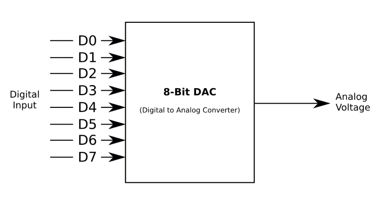
A Digital to Analog Converter commonly referred as DAC, D/A or D2A is a device that converts binary values (0s and 1s) to a set of continuous analog voltages. There are many techniques in which this is done, each with its own advantage and disadvantage. In this article we will learn how a DAC works and how it can be used in out designs.
Where do we need DACs?
A computer is a binary machine operating in an analog world, so to be able to produce an output that is understandable by other devices a DAC is used.
For example, a computer stores audio in the form of binary values of the sound wave. In order to play these back as sound on a speaker we need analog signals, because as we know the speaker’s diaphragm vibrates based on the intensity of the analog signal to produce sound/music. So here, we will a DAC to convert the digital audio file to analog signal in order to play it on a speaker.
DAC Working
The binary system is a positional system, i.e. a place value system, with each bit representing the presence or absence of a certain power of two in the total sum of the powers.
In other words the whole digital to analog conversion process can be thought of as a scaling operation – the binary count is mapped to a certain voltage range, with 0V being the minimum and the maximum voltage being the maximum input binary voltage.
Types of DACs
1. Summing Amplifier
Since digital to analog conversion is simply a weighted sum of the binary input, a circuit called a summing amplifier is used.
This is basically an op-amp amplifier with multiple resistors connected to one input. The junction where the resistors meet is called the summing junction or the virtual ground. The binary input goes into the resistors and the analog output is obtained on the output of the op-amp.
What makes this circuit work is the resistors – each resistor has to be carefully chosen and matched in order to obtain an accurate analog output. The more bits you have, the more different values of resistors you need – and this is not always practical. The limitations can be overcome by using the next method.
2. R-2R Ladder
This is the simplest type of DAC and needs only two resistor values arranged in a ladder. You can think of this as a somewhat complex voltage divider, though the math is quite complex.
The binary input goes into the 2R resistors and the output is obtained at the bottom of the ladder.
3. PWM DAC
This is the type of DAC that most of us have used without even knowing it!
The popular Arduino microcontroller has the capability to output analog signals using a PWM signal. On the outset the PWM signal looks like a binary waveform with only high and low peaks with a variable duty cycle (ratio of on time to time period).
However, this is intended to be used with a RC filter to convert the PWM signal into a voltage value by filtering out the AC component and leaving behind the DC component. The voltage output is proportional to the duty cycle of the input – the higher the duty cycle the greater the output voltage of the filter.
Applications of DACs
1. Digital Signal Processing
It is much easier to work with signals once they have been converted to binary.
A good example of this is audio editing. The audio is converted to binary after which operations can be performed on it. In order to play back this audio, a DAC is used to convert it into a sound signal that can be played back on a speaker.
2. Digital Power Supplies
Most microcontrollers are too slow to be a part of a power supply control loop. In order to change the voltage or current of a power supply, the reference can be changed. This can be done by connecting a DAC to the output of a microcontroller and using that to change the reference voltage to a preselected value.
Drawbacks of DACS
1. Accuracy
DACs can only produce as many voltage steps as the binary number will allow, in other words it is nearly impossible to produce truly continuous voltage values.
2. Complexity
Most of the DAC circuits mentioned above need a few parts and this may not always be practical. However, discrete DAC chips are available that can communicate with a microcontroller through SPI and I2C.
How to use a DAC?
DACs are available as separate ICs or even as embedded into a microcontroller. But the most commonly used ones are the ones that are available as a separate IC. The most commonly used ones are DAC7715, DAC0832, DAC0808 etc.. For the sake of this article let’s consider the MCP4725 DAC IC.
The MCP 4725 is a neat little DAC module that is commonly used in conjunction with the Arduino, and that means good news – documentation and libraries are easily available.
Here are some features of the chip:
1.12 BIT RESOLUTION
This is much better than the 8 bit offered by the Arduino. If the supply voltage is 5V, then each binary digit is converted to a 5V/(2^12) = 1.22mV voltage, which provides amazing resolution. This can be improved by lowering the supply voltage to 3.3V, in which case the resolution is 0.8mV, or 800µV.
2. I2C COMMUNICATION
This communication interface requires only two pins, serial data and serial clock, saving pins on the microcontroller pulling the strings. Speed can range from 100kHz to 3.4MHz.
3. ADDRESS PIN
By either connecting the pin to Vcc or GND, the I2C address can be changed. This is particularly useful when multiple devices are used.
4. PACKAGES:
The MCP 4725 is available in a SOT23-6 package, meaning it’s no smaller than a tiny SMD transistor, which saves a lot of space.
Overall, the MCP 4725 is a powerful chip given the size and features.
Conclusion
DACs form an important link between the analog and digital world and let computers talk to equipment that usually uses analog signals by converting a binary count to a proportional discrete voltage level.


