

Optimized with highly sensitive cap touch sensors, extensive peripheral circuits and 125℃ operation
Introduction to Analog to Digital Converters (ADC Converters)
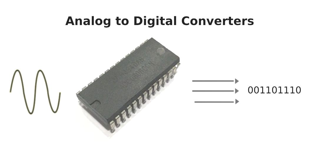
We live in an analog world, surrounded by digital devices. Everything we see, feel or measure is analog in nature such as light, temperature, speed, pressure etc. But most of the electronic devices around us starting from a simple digital watch to a super computer are all digital devices. So, it is obvious that we need something that could convert these analog parameters to digital value for a microcontroller or micro-processor to understand it. This something is called the ADC or Analog to Digital Converter and in this ADC article we will learn more about them.
What is an ADC (Analog to Digital Converter)?
An analog to digital converter is a circuit that converts a continuous voltage value (analog) to a binary value (digital) that can be understood by a digital device which could then be used for digital computation. These ADC circuits can be found as an individual ADC ICs by themselves or embedded into a microcontroller. They’re called ADCs for short.
Why analog to digital converters?
Modern day electronics is purely digital – gone are the good old days of analog computers. Unfortunately for digital systems, the world we live in is still analog and full of colour, not just black and white.
For example a temperature sensor like the LM35 outputs a voltage dependent on the temperature, in the case of that specific device 10mV per degree rise in temperature. If we directly connect this to a digital input, it will register either as a high or a low depending on the input thresholds, which is completely useless.
Instead we use an ADC to convert the analog voltage input to a series of bits that can be directly connected to the data bus of the microprocessor and used for computation.
How does an ADC work?
A good way to look at the working of an ADC is to imagine it as a mathematical scaler. Scaling is basically mapping values from one range to another, so an ADC maps a voltage value to a binary number.
What we need is something that can convert a voltage to a series of logic levels, for example in a register. Of course, registers can only accept logic levels themselves as inputs, so if you were to connect the signal directly to a logic input the results wouldn’t be good. Something in between the logic and the analog input voltage needs to act like an interface.
Here are some important features of ADCs, while going through them we’ll learn how they work.
1. Reference Voltage
Of course, no ADC is absolute, so the voltage mapped to the maximum binary value is called the reference voltage. For example in a 10 bit converter with 5V as the reference voltage, 1111111111 (all bits one, the highest possible 10 bit binary number) correspond to 5V and 0000000000 (the lowest number corresponds to 0V. So each binary step up represents around 4.9mV, since there are 1024 possible digits in 10 bits. This measure of ‘volts per bit’ is called the resolution of the ADC.
What if the voltage changes are below the 4.9mV per step? This puts the ADC in a dead zone, the conversion result therefore always has a small error. This can be prevented by using an ADC with a higher resolution. ADCs up to 24 bits are available, though conversion frequencies are low, in the order of a few hertz.
2. Sample Speed
The number of analog to digital conversions the converter can make every second is called the sample speed. For example a really good ADC can have a sample rate of 300Ms/s. This is to be read as megasamples per second, meaning a million samples per second. Note that SI prefixes apply here.
Sample speed depends completely on the type of converter and the needed accuracy.If a very accurate reading is needed, the ADC usually spends more time looking at the input signal (usually a sample-and-hold or integrating type input), and if accuracy is not a concern they can be quick and dirty with the reading.
The general rule of thumb is, speed and accuracy are more or less inversely proportional, it is important to select an ADC depending on the application.
Types Of ADCs
1. Flash ADC
This is the simplest type of ADC and as the name suggests the fastest. It consists of a series of comparators with the non-inverting inputs connected to the signal input and the inverting pins connected to a voltage divider ladder.
However, if the voltage is above one of the levels of the ladder, all the output bits below the level are set to one, since the voltage is above the threshold for the bottom comparators. To circumvent this problem, outputs are fed through a priority encoder that converts the output to binary.
The speed is limited only by the propagation delays of the comparator and the priority encoder. However, accuracy is moderate.
2. Counting/Slope Integration ADCs
Here, a ramp generating circuit is started at the time of conversion and a binary counter is started at the same time. A comparator detects when the ramp goes above the input voltage and stops the binary counter. The binary count obtained is proportional to the input voltage level.
The absolute accuracy of this converter is questionable, however it gives good resolution and even spacing between the binary steps while being simple to implement. If no chips are available, this circuit can even be made discretely.
3. Successive Approximation ADCs
These ADCs are perhaps the most accurate. They consist of a comparator, a simple flash DAC and a memory register. The device initially assumes all the bits in the register except for the highest significant bit (which is a one) to be zeroes. The register then sends this to the DAC which converts it to an analog voltage, which is compared with the input through the comparator. If the input voltage is higher than the DAC voltage, then the MSB remains one. This process repeats until all the bits have been set either to zero or one, in other words till the register value exactly equals the input voltage.
This ADC is one of the most commonly used where accuracy is needed and speed is not too much of a limitation, for example in microcontrollers. SA type ADCs can easily achieve conversion times of a few microseconds.
Applications
1. Digital Oscilloscopes and Multimeter
The greatest advantage of analog oscilloscopes is that there’s very little ‘circuitry’ between the input connector and the screen, in other words you see exactly what’s going on in a circuit in real time. However, they cannot store waveforms for later use or perform on-board measurements.
Digital oscilloscopes overcome all these problems and at their heart lies a very powerful and fast ADC with a resolution of 12 bits and above. The ADC converts the waveforms to a binary value that can be stored in memory, operated upon and displayed on a screen.
2. Microcontrollers
Almost all modern microcontrollers have a built in ADC, the most common being the Arduino based on the ATMega328P with a 10 bit resolution and the STM32 with a 12 bit resolution.
The Arduino IDE provides a useful ‘analogRead()’ function that reads an analog voltage on one of the analog pins and returns a 10 bit integer value, i.e. a range of 0 to 1023.
3. Digital Power Supplies
Most power supplies these days are computer controlled, and for the computer to measure the voltage output an ADC is needed.
How to use an ADC IC?
There are many ADC ICs available in the market which can be used along to measure analog voltages. The ADC0804, ADC0808, MCP3008 etc are few of the most used ADC modules. They are commonly used along with Raspberry pi and other processor or digital circuit where an In-built ADC is not available. For example let’s consider the ADS1115 ADC IC from Texas Instruments which has high resolution and modern architecture.
It comes in either a QFN or a VSSOP package, allowing for a very small form factor – it takes up nearly no space on a PCB.This little chip does it all – we’ll take a look at some of its features below.
1. I2C Compatibility
Anyone who has worked with microcontrollers knows how useful the SPI and I2C bus can be to communicate with peripherals. This feature makes it very easy to use this IC with an Arduino board since extensive libraries have been written for the device.
2. Power Consumption
The advantage to using any modern IC is that they consume very low currents and operate over a wide range of voltages, in this case 2.0V to 5.5V. Beware of the fine print under the 150uA current, it’s for continuous conversion mode.
3. Programmable Comparator
The ADS comes with a comparator whose reference can be programmed over the I2C bus. Of course for fast application nothing beats a discrete comparator IC.
4. Configurable Inputs
The four inputs can either be two differential pairs (only the voltage difference across those pins is taken into account) or four single ended inputs.
Another nice thing about this IC is that it’s quite popular among hobbyists, which makes documentation and example code easy to find.
Drawbacks of ADCs
1. ADCs are slow, typically in the order of a few micro or nanoseconds.
2. Lack of continuous voltage values.
3. Circuit complexity increases


