

Optimized with highly sensitive cap touch sensors, extensive peripheral circuits and 125℃ operation
Design Guide - PMOS MOSFET for Reverse Voltage Polarity Protection

If the power source of the circuit is reversed, for example, connecting the positive wire into the ground and the negative wire into the circuit’s Vcc. Two bad things could happen, either the circuit that we designed can get burned along with all the expensive components in it, or the power source by itself can get destroyed. Things get even more dangerous if the circuit is powered by a battery. Reversing the polarity of a battery is the worst thing that can happen in a circuit because it will not only damage the circuit but can also cause smoke and fire making it a potential threat.
But human error can occur and hence it is the responsibility of the designer to ensure his circuit can handle reverse polarity conditions safely. This is why almost all circuits have an additional safety circuit on its input side called reverse polarity protection circuit. In this article, we will discuss a MOSFET reverse polarity protection circuit that is very efficient to protect the circuit from reverse polarity related damages. The circuit can also act as a battery polarity protection circuit, so the same design guide can be used for protecting your circuits even if it is powered by an external DC adapter or a Battery.
Protecting Circuits from Reverse Polarity
There are several options to protect the circuit from reverse polarity. Most of the time, battery-operated devices use special types of battery connectors that do not allow the battery connector to connect in reverse order. This is a mechanically possible reverse polarity protection for the battery. Another choice is to use a Schottky diode in the power rail but that is the most inefficient way to protect the circuit from reverse polarity.
Using Schottky Diode for Polarity Protection and its Disadvantages
In the below image, a Schottky diode is used in series with the power rail that will get reverse biased during reverse polarity condition and disconnect the circuit. We have also previously discussed this in the Application of Diodes section in a previous article.
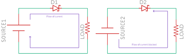
The left image is the proper connection of the polarity but the right image is the reverse polarity condition. During the reverse polarity connection, the Schottky diode blocks the flow of current.
But, the above circuit is inefficient due to the constant flow of load current through the Schottky diode. Also, the voltage across the output of the Schottky diode is less than the input voltage due to the forward voltage drop of the diode. So, by using the above method, it will protect the circuit from reverse polarity protection but not in an efficient way.
The proper way to make a reverse polarity protection circuit is by using a simple PMOS MOSFET or NMOS MOSFET. It is advisable to use PMOS because PMOS cuts off the positive rails and the circuit will not get any voltage and there are fewer chances of harmful consequence if the circuit works at high DC voltages.
PMOS MOSFET for Reverse Voltage Protection
The field-effect transistor (FET) is a type of transistor that uses an electric field to control the flow of current through it. FETs are devices with three terminals that are source, gate, and drain. FETs control the flow of current by the application of a voltage to the gate, which in turn alters the conductivity between the drain and source. This is the basic thing that is used in P-MOSFET as a switch in reverse polarity protection.
The below figure shows the PMOS reverse polarity protection circuit.
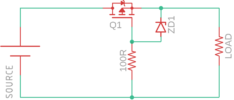
The PMOS is used as a power switch that connects or disconnects the load from the power supply. During the proper connection of the power supply, the MOSFET turns on due to the proper VGS (Gate to Source Voltage). But during the Reverse polarity situation, the Gate to Source voltage is too low to turn on the MOSFET and disconnects the load from the input power supply.
The 100R resistor is the MOSFET gate resistor connected with the Zener diode. The Zener diode protects the gate from overvoltage.
Actual Simulation in Orcad PSPICE
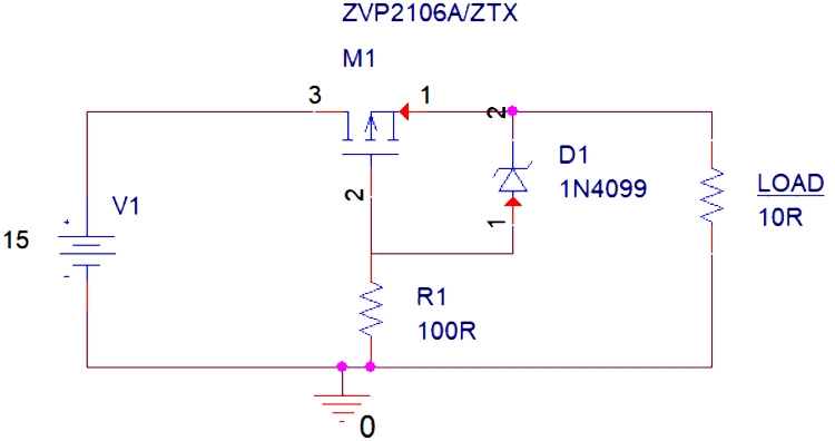
The above circuit has all the required components for reverse polarity protection. The V1 is the source that is in perfect polarity. The P-Channel MOSFET is getting biased from the Resistor 100R and the 6.8V Zener diode 1N4099. The Load is a 10R resistor.
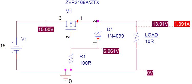
The simulation shows the circuit is working properly in the right polarity of the power supply. The Zener diode protects the gate from the overvoltage and the load is getting 1.3A with 13.9V.
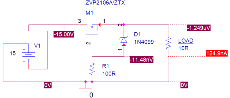
In the above image, the source is reversed. The Load is turned off completely and the circuit is acting as a reverse polarity protector. You can also check out the video below which explains the working of the circuit with simulation:
Selecting MOSFET for Reverse Polarity Protection
It is advisable to use PMOS over NMOS. This is because PMOS is used in the positive rail of the circuit rather than the Negative rail. Therefore, PMOS cuts off the positive rails and the circuit will not have any positive voltage. But, NMOS is used in negative rails, thus disconnecting the negative rail do not disconnect the circuit from the batteries positive rail. Therefore, in the case of high voltage DC, disconnecting the positive rail is much safer than disconnecting the negative rail and there are fewer chances of harmful consequences like short circuits, electrocution, etc. will not happen.
The component selection is an important part of this circuit. The main component is the P channel MOSFET.
A MOSFET has the following specs that are crucial for the circuit.
- Drain Source Resistance (RDS)
- Drain Current
- Drain to source voltage
Drain Source Resistance (RDS):
RDS is the Drain to source resistance. Use a very low RDS (Drain to source resistance) for low heat dissipation and the very low voltage drop across the output. Higher RDS will produce higher heat dissipations.
Drain Current:
This is the maximum current that will pass through the MOSFET. Therefore, if the load circuit requires 2A of current, choose a MOSFET that will withstand this current. In such a case, Mosfet with a drain current of 3A will be a good choice. Choose this parameter larger than the actual required.
Drain to Source Voltage:
Drain to source voltage of the MOSFET needs to be higher than the circuit voltage. If a circuit requires a maximum of 30V, a MOSFET with a drain to source voltage of 50V is required for safe operations. Always choose this parameter larger than the actual required.
During reverse polarity, the MOSFET will be turned off due to the insufficient Vgs, and there will be no effect on the load circuit as well as the MOSFET. The above parameters are required during the normal condition and need to be carefully selected.
Selection of the Zener Diode Voltage:
Each MOSFET comes with a Vgs (gate to source voltage). If the gate to source voltage increases than the maximum rating, this can damage the MOSFETs gate. Therefore, choose a Zener diode voltage that will not exceed the gate voltage of the MOSFET. For a Vgs of 10V, 9.1V Zener diode will be sufficient. Make sure that the gate voltage should not cross the maximum voltage rating.
100R Resistor in the Circuit:
The resistor value needs to be chosen in a way that it should not be high enough to not overheat the Zener, but low enough to provide adequate Zener bias current and to discharge the Gate rapidly if the supply voltage is suddenly reversed. Therefore, here is a tradeoff between the Gate discharge time and Zener biasing. In most cases, 100R-330R is good if there are chances for the appearance of sudden reverse voltage in the circuit. But if there are no chances of sudden reverse voltage during the continuous working of the circuit, anything from the 1k-50k resistor value can be used.
Part Number Suggestion:
The most popular MOSFETs that are used for a wide range of reverse polarity protection-related circuits-
- IRF9530
- IRF9540
- Si2323 (Low Voltage Low Current Operations)
- ILRML6401 (Low Voltage Low Current Operations)
Drawbacks of MOSFET Reverse Polarity Protection Circuit
The main drawback of this circuit is the power dissipation across the MOSFET. However, that can be solved using a P channel MOSFET that has RDS on resistance in milliohms.


