BTA16 600V/800V 16A TRIAC Pinout, Specifications, Equivalent & Datasheet
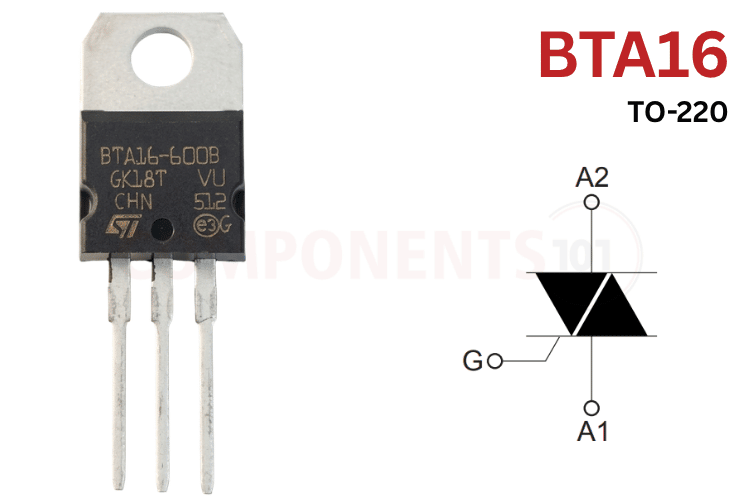
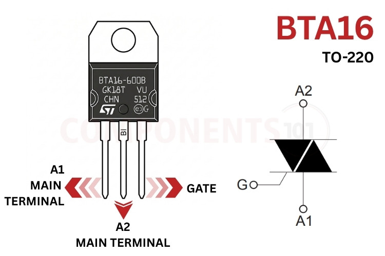
BTA16 Pinout Configuration
The BTA16 pinout is manufactured in a standard 3-pin TO-220AB package with the following pin assignment:
| Pin Number | Pin Name | Description |
| 1 | A1 (Main Terminal 1 / MT1) | Main power terminal 1. Acts as the primary voltage reference for gate triggering signals. |
| 2 | A2 (Main Terminal 2 / MT2) | Main power terminal 1. Acts as the primary voltage reference for gate triggering signals. |
| 3 | G (Gate) | Trigger terminal. Sinking or sourcing gate current relative to A1 triggers the TRIAC into conduction. |
| Tab | Insulated Tab | Electrically isolated mounting tab rated up to 2500 VRMS. Can be safely bolted directly to chassis ground. |
*Note: On the complementary BTB16 series (non-insulated variant), the mounting tab is electrically connected to Pin 2 (A2 Main Terminal).
BTA16 vs BTB16 and Suffix Coding Differences
STMicroelectronics and other licensed manufacturers produce the 16A TRIAC series in multiple variations. Deciphering the part number markings is essential for selecting the appropriate device for resistive versus inductive loads.
| Part Number Suffix | Isolation Type | Peak Voltage (VDRM) | Gate Sensitivity (IGT) | Commutation Quadrants | Primary Application |
| BTA16-600B | Insulated (2500 VRMS) | 600V | 50 mA | 4-Quadrant (Standard) | General-purpose AC switching, heating elements, resistive lamp dimming. |
| BTA16-800B | Insulated (2500 VRMS) | 800V | 50 mA | 4-Quadrant (Standard) | 230V/240V industrial AC switching with high transient voltage margins. |
| BTA16-600BW | Insulated (2500 VRMS) | 600V | 50 mA | 3-Quadrant (Snubberless) | Inductive loads, universal AC motors, compressor relays, fan speed controls. |
| BTA16-800BW | Insulated (2500 VRMS) | 800V | 50 mA | 3-Quadrant (Snubberless) | Heavy industrial inductive loads, high-voltage HVAC motors without RC snubbers. |
| BTA16-600CW | Insulated (2500 VRMS) | 600V | 50 mA | 3-Quadrant (Snubberless) | Sensitivity gate: inductive AC switching, vacuum cleaners, power tool speed control. |
| BTB16-600B | Non-Insulated (Tab = A2) | 600V | 50 mA | 4-Quadrant (Standard) | High thermal dissipation design requiring the lowest thermal resistance (Rth(j-c) = 1.2 °C/W). |
BTA16 Key Features & Specifications
- Device Type / Category: Bidirectional Triode Thyristor (AC TRIAC)
- RMS On-State Current (IT(RMS)): 16A (at TC = 86°C for TO-220AB Insulated, TC = 100°C for Non-Insulated)
- Repetitive Peak Off-State Voltage (VDRM / VRRM): 600V (BTA16-600) / 800V (BTA16-800)
- Non-Repetitive Surge Peak Current (ITSM): 160A (50 Hz, tp = 20 ms) / 168A (60 Hz, tp = 16.7 ms)
- I2t Value for Fusing (I2t): 144 A²s (tp = 10 ms, Tj initial = 25°C)
- Gate Trigger Current (IGT): 50 mA max for B/BW variants; 35 mA max for CW; 25 mA max for C (at VD = 12V, RL = 33 Ω)
- Gate Trigger Voltage (VGT): 1.3V max (at VD = 12V, RL = 33 Ω, all quadrants)
- Peak On-State Voltage Drop (VT): 1.55V max at ITM = 22.5A, tp = 380 µs, Tj = 25°C
- Holding Current (IH): 50 mA max (B/BW versions); 25 mA max (C versions) at IT = 500 mA
- Package Type: TO-220AB (Through-Hole 3-Lead Insulated Package)
*Note: Complete Technical Details can be found in the BTA16 datasheet given at the end of this page.
BTA16 Equivalent & Alternative Components
When looking for a BTA16 equivalent, match four things: voltage rating, gate current, quadrant type (standard or snubberless) and insulation. The table below lists the most common replacements.
| Equivalent Part | Isolation Type | Key Ratings | Description & Compatibility Notes |
| BTB16-600B | Non-Insulated | 600V, 16A, IGT = 50mA, TO-220AB | Non-insulated counterpart. Tab is internally connected to A2; offers lower thermal resistance (1.2 °C/W). |
| BTA16-800B | Insulated | 800V, 16A, IGT = 50mA, TO-220AB | Direct high-voltage sibling offering higher transient surge headroom for 230V/240V utility grids. |
| BTA12-600B | Insulated | 600V, 12A, IGT = 50mA, TO-220AB | Lower-current 12A insulated sibling for compact AC loads up to 2.5 kW. |
| BTA24-600B | Insulated | 600V, 25A, IGT = 50mA, TO-220AB | Higher-current 25A heavy-duty upgrade for large commercial heaters and induction motors |
| BT139-600E | Non-Insulated | 600V, 16A, IGT = 10mA, TO-220AB | Sensitive-gate 16A 4-quadrant TRIAC from WeEn / NXP; requires heatsink isolation hardware. |
| T1635-600G | Surface Mount | 600V, 16A, IGT = 35mA, D2PAK | Snubberless surface-mount SMD replacement for automated SMT manufacturing. |
What Is the BTA16 Triac?
The BTA16 Triac is one of the most widely deployed AC solid-state power switches in modern industrial and consumer electronics. Unlike conventional bipolar transistors or MOSFETs that conduct in a single direction and turn OFF as soon as the base or gate drive is removed, a TRIAC is a multi-layer bidirectional AC silicon semiconductor. Once fired by a momentary pulse of gate current (IGT ≥ 50 mA), the BTA16 latches into a low-impedance ON state for both the positive and negative half-cycles of the AC mains waveform, continuing to conduct until the AC load current naturally crosses zero.
Key operational characteristics of the BTA16 include:
1. Galvanically Isolated Mounting Tab: The metallic mounting flange is separated from the active silicon die by an internal aluminum oxide ceramic substrate rated for 2500 VRMS breakdown. This eliminates the necessity of external mica or Kapton insulation hardware, which degrades thermal conductivity over time and risks dielectric puncture under high AC line surges.
2. Standard 4-Quadrant vs Snubberless 3-Quadrant Operation: Standard BTA16-B models trigger in all four quadrants (QI, QII, QIII, and QIV). However, triggering in Quadrant IV (where A2 is negative and Gate is positive relative to A1) has lower gate sensitivity and slower turn-off recovery. In the Snubberless "W" models (BTA16-BW and BTA16-CW), Quadrant IV triggering is eliminated by design. By optimizing internal silicon recombination, Snubberless TRIACs achieve exceptionally high commutating dV/dt (up to 1000 V/µs) and withstand the phase displacement of heavy inductive loads (such as AC motors, ceiling fans, and transformers) without false triggering or requiring an external RC snubber network.
BTA16 Datasheet
The complete original manufacturer electrical characteristics, safe operating area (SOA), quadrant triggering curves, and thermal impedance characteristics are available in the BTA16 datasheet.
BTA16 Circuit Diagram: Opto-Isolated AC Switching
To interface the BTA16 circuit diagram with modern 3.3V or 5V microcontrollers (such as ESP32, STM32, Arduino, or Raspberry Pi Pico), optical galvanic isolation must be established between the sensitive low-voltage digital microcontroller and the high-voltage 230V AC mains lines.
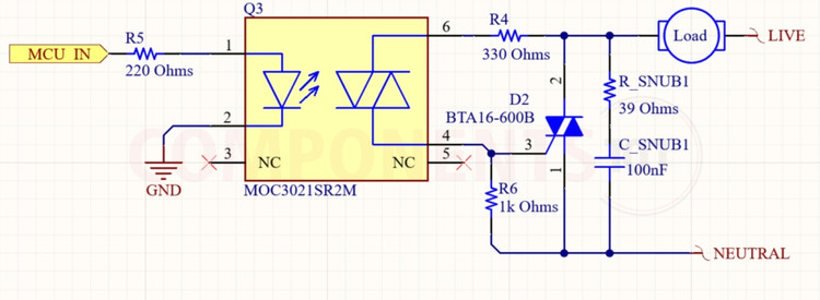
Circuit Operation & Component Selection
1. Microcontroller Drive & Current Limiting Resistor (R1 = 220 Ω):
The digital GPIO pin of the microcontroller drives the infrared-emitting diode inside the optotriac. With a 3.3V or 5V logic signal, resistor R1 sets the forward current to approximately 10 mA to 15 mA (VF ≈ 1.2V), providing reliable optical triggering across operating temperatures without overloading the microcontroller pin.
2. Opto-TRIAC Driver IC (MOC3021 / MOC3041):
An optoisolator provides an optical isolation barrier rated for up to 5000V, protecting low-voltage embedded systems from high-voltage AC surges:
- MOC3041 / MOC3063 (Zero-Crossing Driver): Preferred for ON/OFF power control, solid-state relays (SSRs), and heating elements. It automatically delays conduction until the AC voltage waveform crosses zero, virtually eliminating electromagnetic interference (EMI) and current inrush transients.
- MOC3021 / MOC3023 (Random-Phase Driver): Mandatory for phase-angle cut dimming circuits (such as lamp dimmers and AC motor speed controllers), allowing the microcontroller to trigger the BTA16 at any arbitrary point along the 50 Hz/60 Hz AC sine wave.
3. Gate Current-Limiting Resistor (R2 = 330 Ω, 0.5W):
Resistor R2 is placed in series between Main Terminal A2 and the BTA16 Gate via the optotriac output stage. When the internal optotriac fires, R2 limits the instantaneous peak trigger current drawn from the AC line to safe levels (below 1A), ensuring rapid gate saturation while shielding the internal detector from overcurrent damage.
4. Gate-to-A1 Noise Suppression Resistor (R3 = 1 kΩ):
Connected directly across the Gate and A1 Main Terminal, resistor R3 bleeds away leakage currents and suppresses high-frequency capacitive noise induced across the gate junction during rapid voltage transients, preventing false spurious triggering on noisy mains lines.
5. RC Snubber Network (R_SNUB = 39 Ω 2W, C_SNUB = 100 nF 400V):
When driving inductive loads (such as electric motors, solenoid valves, or transformers), the AC load current lags behind the supply voltage. When the TRIAC current crosses zero and turns OFF, a steep rate of rise of voltage (dV/dt) appears abruptly across A1 and A2. The series RC snubber network absorbs this inductive energy and dampens the dV/dt slope below 400 V/µs, preventing unintentional re-triggering.
*Note: When using Snubberless models like the BTA16-600BW, this external RC snubber network can be safely omitted for most moderate motor loads.
BTA16 Applications
- Solid-State Relays (SSRs): Silent, spark-free AC line switching replacing mechanical contactors in industrial machinery and commercial ovens.
- AC Light Dimmers: Phase-angle power regulation in architectural lighting, stage incandescent lamps, and dimmable halogen fixtures.
- Appliance Motor Speed Control: Variable speed modulation for washing machine motors, vacuum cleaners, kitchen blenders, and ceiling fans.
- Industrial Temperature Regulators: Proportional-integral (PID) power control for plastic extrusion heaters, soldering stations, and drying tunnels.
- Soft-Start AC Motor Starters: Limiting startup inrush currents in single-phase induction motors, water pumps, and air compressors.
- Mains Static Switching & Transfer Switches: Automatic AC bus transfer switches and uninterrupted power supply (UPS) bypass circuits.
BTA16 TO-220AB 2D Model and Component Dimensions
For hardware design engineers drafting custom PCB layouts or footprint libraries in CAD tools (KiCad, Altium Designer, Eagle, EasyEDA), the physical dimensions for the standard TO-220AB (Insulated) package are given below (conforming to STMicroelectronics Figure 13 and Table 6):
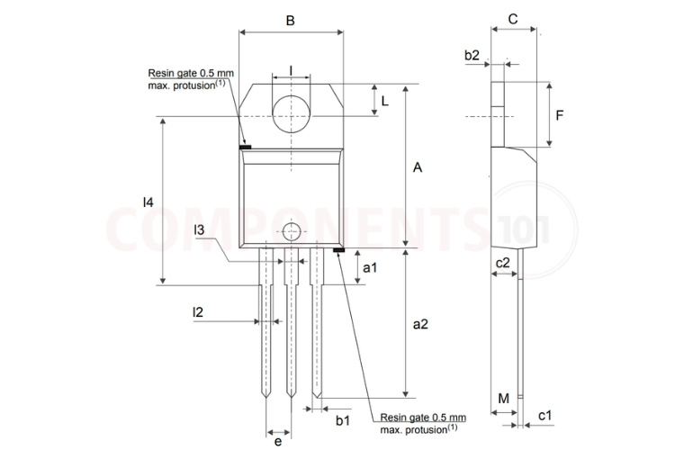
| Parameter Symbol & Description | Minimum (mm) | Typical (mm) | Maximum (mm) |
| A (Total Body Length / Height) | 15.20 | - | 15.90 |
| a1 (Lead Shoulder Length) | - | - | - |
| a2 (Lead Length Below Seating Plane) | 13.00 | - | 14.00 |
| B (Total Molded Body Width) | 10.00 | - | 10.40 |
| b1 (Center Lead Width, Lead 2) | 0.61 | - | 0.88 |
| b2 (Mounting Tab Thickness) | 1.23 | - | 1.32 |
| C (Package Thickness / Total Depth) | 4.40 | - | 4.60 |
| c1 (Lead Thickness) | 0.49 | - | 0.70 |
| c2 (Lead Offset / Base to Seating Plane) | 2.40 | - | 2.72 |
| e (Lead Pitch / Pin Spacing) | 2.40 | - | 2.70 |
| F (Mounting Tab Height) | 6.20 | - | 6.60 |
| I (Mounting Hole Diameter) | 3.73 | - | 3.88 |
| L (Hole Center to Top Edge Distance) | 2.65 | - | 2.95 |
| l2 (Outer Leads Width, Lead 1 & 3) | 1.14 | - | 1.70 |
| l3 (Center Lead Shoulder Width) | 1.14 | - | 1.70 |
| l4 (Hole Center to Lead Shoulder Distance) | 15.80 | 16.40 | 16.80 |
| M (Lead Stagger / Bottom Offset) | - | 2.60 | - |