TL594 PWM Controller
The TL594 is a high-performance fixed-frequency Pulse-Width-Modulation controller IC. This IC is designed primarily for power-supply control, this device offers the flexibility to tailor the power-supply control circuitry to a specific application. It is an upgraded version of the well-known TL494 PWM controller. TL594 can be adapted to various power conversion needs, including step-up step-down and inverting configurations. It has a wide input voltage range, which means the TL594 can be used for different applications. The TL594 has two error amplifiers, an on-chip adjustable oscillator, a dead-time control (DTC) comparator, a pulse-steering control flip-flop, a 5-V regulator with a precision of 1%, an undervoltage lockout control circuit, and an output control circuitry. This IC is available in SOIC, SO, PDIP, and TSSOP packages.
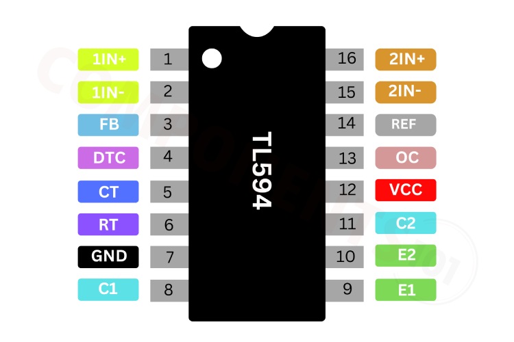
TL594 Pinout Configuration
Here are the pinout details for TL594.
| NO | NAME | DESCRIPTION |
| 1 | 1IN+ | Noninverting input to error amplifier 1 |
| 2 | 1IN– | Inverting input to error amplifier 1 |
| 3 | FEEDBACK | Input pin for feedback |
| 4 | DTC | Dead-time control comparator input |
| 5 | CT | Capacitor terminal used to set oscillator frequency |
| 6 | RT | Resistor terminal used to set oscillator frequency |
| 7 | GND | Ground |
| 8 | C1 | Collector terminal of BJT output 1 |
| 9 | E1 | Emitter terminal of BJT output 1 |
| 10 | E2 | Emitter terminal of BJT output 2 |
| 11 | C2 | Collector terminal of BJT output 2 |
| 12 | VCC | Positive supply |
| 13 | OUTPUT CTRL | Selects single-ended, parallel output, or push-pull operation |
| 14 | REF | 5-V reference regulator output |
| 15 | 2IN– | Inverting input to error amplifier 2 |
| 16 | 2IN+ | Noninverting input to error amplifier 2 |
Manufacturers of TL594:
The TL594 is originally manufactured by TEXAS INSTRUMENTS.
TL594 Equivalents
If you are looking for a pin-compatible PWM controller for TL594 then you can use TL494
TL594 Alternatives
If you are looking for an alternative for TL594 you can look at the other ICs from these.
UC3842, UC3843, UC3844, TL3842, UC2842, SG2524, SG3525
Note: Complete technical details can be found in the TL594 datasheet at this page’s end.
Features of TL594
TL594 PWM controller has the following key features:
- Complete PWM Power-Control Circuitry
- Uncommitted Outputs for 200-mA Sink or Source Current
- Output Control Selects Single-Ended or Push-Pull Operation
- Internal Circuitry Prohibits Double Pulse at Either Output
- Variable Dead Time Provides Control Over Total Range
- Internal Regulator Provides a Stable 5-V Reference Supply Trimmed to 1%
- Circuit Architecture Allows Easy Synchronization
- Undervoltage Lockout (UVLO) for Low-VCC Conditions
TL594S schematics
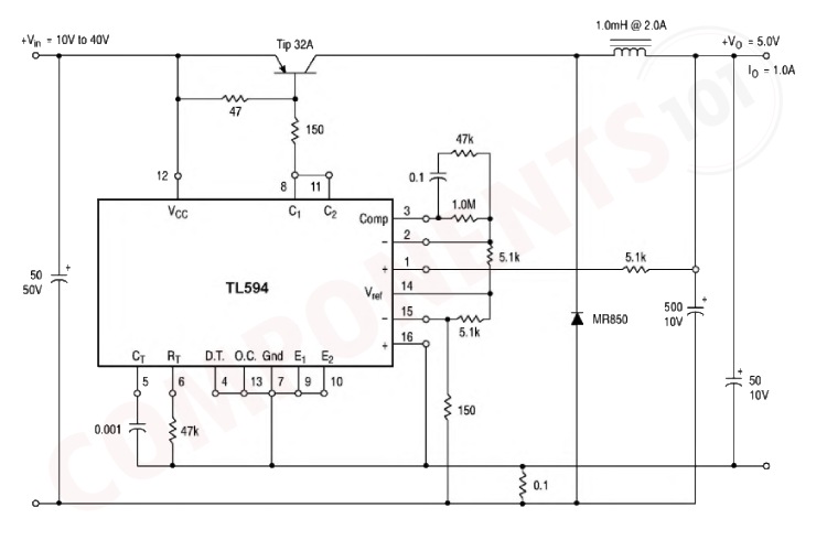
The above circuit diagram shows a typical regulator circuit using a TL594 PWM controller.
In this circuit, the Power supply is connected to the VCC pin of TL594. The power supply ground is connected to the Ground of the controller. RT and CT pins are used to set the oscillator frequency. The resistor (47kΩ) and capacitor (0.001µF) determine the switching frequency. In the output section, a TIP32A power transistor is used to switch the input voltage. The inductor stores energy when the transistor is on and releases it when the transistor is off, smoothing the output current. Schottky Diode prevents the inductor from discharging back into the power supply when the transistor is off. The Output capacitors filter the output voltage to reduce ripple and provide a stable 5V output. The voltage divider (47kΩ, 1MΩ, 5.1kΩ) scales down the output voltage to a level suitable for the error amplifier input. The error amplifier compares the scaled-down output voltage to the reference voltage (5V) and adjusts the PWM signal to regulate the output voltage.
Troubleshooting Tips for TL594
I designed a voltage regulator with a TL594 PWM controller, but not getting any output from the circuit?
First, check if the power supply voltage matches the circuit requirements. Ensure proper grounding. Then use an oscilloscope to check the PWM signal at various points in the circuit. Look for distortions, incorrect duty cycles, or missing signals. Finally, measure voltages at key points in the circuit and compare them to expected values based on the schematic.
I am getting distorted Signals, what could be the reason?
This can be caused by noise on the power supply, incorrect component selection, grounding issues faulty timing components (resistors, capacitors) or a problem with the control signal driving the PWM generator. Check one by one to find the correct issue.
why your PWM circuit is not providing current as expected?
There could be several reasons why your PWM circuit is not providing current as expected.
Ensure that the power supply is functioning correctly and providing the necessary voltage and current for your circuit. Double-check all connections to make sure there are no loose or incorrect connections. Verify that the PWM signal is being generated correctly. Use an oscilloscope or a multimeter with a frequency measurement function to check the signal at the output pin of the PWM controller. Make sure that the duty cycle of the PWM signal is set correctly. A very low-duty cycle might result in a very small average current.
Design Tips for TL594
Power Supply Recommendations-The TL494 is designed to operate from an input voltage supply range between 7 V and 40 V. This input supply should be well regulated. If the input supply is located more than a few inches from the device, additional bulk capacitance may be required in addition to the ceramic bypass capacitors. A tantalum capacitor with a value of 47 μF is a typical choice, however, this may vary depending on the output power being delivered.
Layout Guidelines- Always try to use a low EMI inductor with a ferrite-type closed core. Some examples would be toroid and encased E-core inductors. The open core can be used if they have low EMI characteristics and are located a bit away from the low power traces and components. Make the poles perpendicular to the PCB as well if using an open core. Stick cores usually emit the most unwanted noise.
- Feedback Traces Try to run the feedback trace as far from the inductor and noisy power traces as possible. The feedback trace should be as direct as possible and somewhat thick. These two sometimes involve a trade-off but keeping it away from inductor EMI and other noise sources is the more critical of the two. Run the feedback trace on the side of the PCB, opposite to the inductor with a ground plane separating the two.
- Input/Output Capacitors When using a low-value ceramic input filter capacitor, it should be located as close to the VCC pin of the IC as possible. This will eliminate as many trace inductance effects as possible and give the internal IC rail a cleaner voltage supply. Some designs require the use of a feed-forward capacitor connected from the output to the feedback pin as well, usually for stability reasons. In this case, it should also be positioned as close to the IC as possible. Using surface-mount capacitors also reduces the lead length and lessens the chance of noise coupling into the effective antenna created by through-hole components.
- Compensation Components External compensation components for stability should also be placed close to the IC. Surface mount components are recommended here as well for the same reasons discussed for the filter capacitors. These should not be located very close to the inductor either.
Applications of TL594
- Power Supplies
- Server PSUs
- SMPS circuits
- Solar Micro-Inverters
- Solar Power Inverters
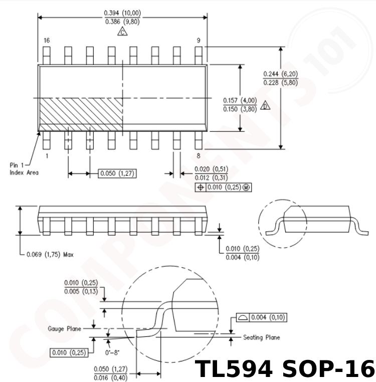
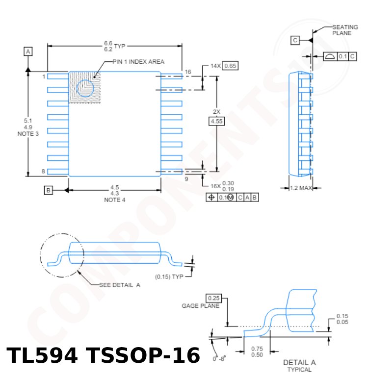
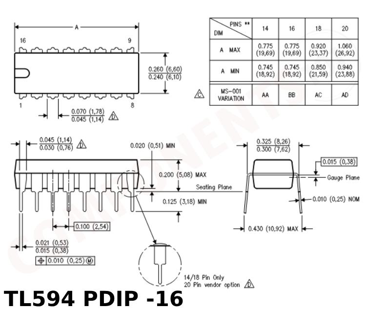
2D Model and Dimensions of TL594
Here you can find the mechanical drawings of TL594 along with its dimensions. The dimensions can be used to create custom footprints of the module and be used for PCB or CAD modelling.